Glossary#
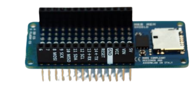
- Arduino MKR Connector Carrier#
An electronic board designed to facilitate the connection of various modules to the data logger (Grove connection). It incorporates voltage adapters (5V / 3.3V) as well as the main power supply (5V).
- Arduino MKR MEM Shield#
An electronic board that allows measured data to be saved to a memory card (microSD). It also has flash memory for saving sensor calibration coefficients or calibration rates when necessary.
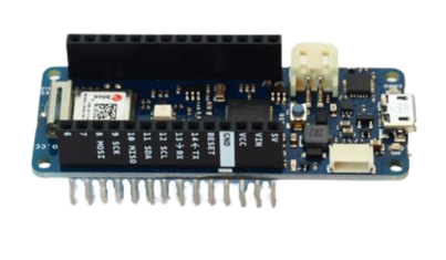
- Arduino MKR Wifi 1010#
Electronic board, the SETIER control unit’s microcontroller, which manages the control of peripherals, measurement and data logging. It is the heart of the control unit. It also incorporates the Wi-Fi chip that generates the data logger’s web page.
- Box#
box containing the components of the SETIER control unit.
- WAGO terminal block#
Transparent lever-type terminal block for connecting any type of electrical wire.
- Screw terminal block#
A connector comprising screws and metal terminals into which an electrical wire is inserted and clamped by a screw to ensure electrical contact.
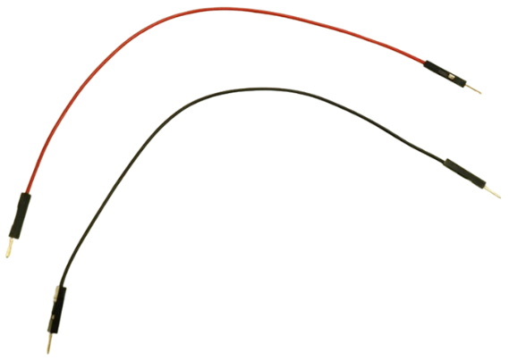
- Picot cable#
A pin-type 2-pin connector for connecting various components.
- Setier Station#
The unit consists of a data logger, peripheral electronic modules and measurement sensors, all housed in a single enclosure.

- Grove connector#
White 4-pin ribbon connector (male or female version) found on various peripheral modules, as well as on the Arduino MKR Connector Carrier board.
- Datalogger#
Data logger comprising Arduino MKR Wifi 1010, Arduino MKR MEM Shield and Arduino MKR Connector Carrier boards. These are supplemented by a Gravity RTC module for managing the date and time, a Grove Voltage Divider module for managing the unit’s power supply, and a push-button to activate the Wi-Fi interface.
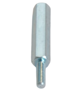
- Spacer#
A component placed between two parts to keep them at a specific distance apart.
- I2C#
A serial communication bus that enables a microcontroller to communicate with multiple devices (sensors, displays, memory modules, etc.) using just two wires.
- Jack#
A cylindrical male connector with axial insertion, used to establish an analogue connection between electronic devices. It usually has 2 or 3 contacts.
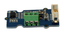
- Module Current to Voltage#
An electronic circuit board that converts the current supplied by a system (in this case, a pressure sensor) into voltage.
- Module Gravity RTC#
An integrated real-time clock circuit built into the Gravity system, which ensures continuous tracking of the date and time even when the main power supply is disconnected, thanks to a backup battery. It provides other system components with accurate and reliable time-stamping.
- Module Grove I2C Multiplexer#
An electronic board that allows you to connect various modules using I2C as the communication protocol.
- Module Grove 4 Relay#
Relays controlled by the data logger to supply power to up to four components.
- Module Grove Relay#
A relay controlled by the data logger to supply power to a component or not.
- Module Grove RS485#
An electronic board for connecting various modules using the RS485 communication protocol. This board converts the RS485 signal to UART, which is read by the data logger.
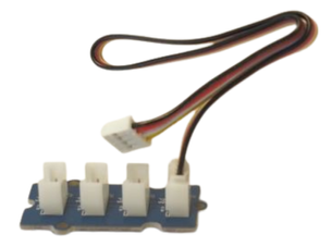
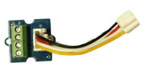
- Module Grove Screw Terminal#
4-terminal screw terminal block for connecting two cables of different types.
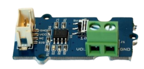
- Module Grove Voltage Divider#
Electronic voltage divider board for stepping down the voltage from 12 V to 5 V.
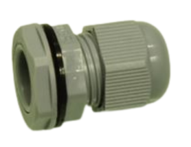
- Cable gland#
A device used to feed a cable through a wall whilst ensuring it is sealed and held securely within the housing.
- Communication protocol#
A set of formally defined rules and conventions governing the exchange of data between two or more entities (components, devices, systems). It specifies the format of messages, the sequence of exchanges, error handling and synchronisation mechanisms, thereby ensuring reliable interoperability between potentially heterogeneous equipment. Common examples: I²C, RS485, UART, USB.
- RS485#
A serial communication standard that enables multiple devices to communicate with one another via two wires, using a differential signal. This communication is possible over long distances (up to 1,200 m) and at high data rates. Unlike the conventional UART, it uses two wires (A and B) carrying opposite voltage signals, making it particularly resistant to electromagnetic interference. It supports a multipoint bus topology, allowing up to 32 nodes (transmitters and receivers) to be connected on the same line. Widely used in industrial environments, it is notably employed as the physical layer of the Modbus protocol.
- UART (Universal Asynchronous Receiver Transmitter)#
An asynchronous serial communication protocol that enables data exchange between two devices via two unidirectional lines: TX (transmission) and RX (reception). Unlike synchronous protocols, it does not require a shared clock signal — synchronisation is achieved through a communication rate (baud rate) agreed in advance between the two parties. Each data frame is delimited by a start bit and one or more stop bits. Simple to implement, the UART is widely used in embedded systems for communication between microcontrollers, sensors and peripheral modules.