Flowmeter#
Mounting information
Refer to this document to assemble the SETIER Flow central. The cost of equipment needed for assembly as of 09/02/2026 is €358.71 (for a unit with 2 sensors). The time required for assembly and programming is 6 hours. For this assembly, you should be in a well‑lit quiet room, some steps may be meticulous. Ensure you have all the equipment and tools before starting assembly. Tool and equipment lists are provided in the following documentation.
Information
SETIER is an open collaborative project. However, assembling the associated :term`Centrale Setier` units requires adherence to safety rules for electronic board usage. :term`Centrale Setier` units must be assembled in a professional environment by individuals with electronics knowledge. The SETIER team cannot in any case be liable for any material or human damage that may arise during assembly or use of a Centrale Setier. Furthermore, the SETIER team cannot be held responsible if the :term`Centrale Setier` fails after assembly.
You may redistribute and modify this documentation and create products using it under the terms of the CERN‑OHL‑P v2 (https://cern.ch/cern-ohl). This documentation is distributed WITHOUT ANY EXPRESS OR IMPLIED WARRANTY, INCLUDING MERCHANTABILITY, SATISFACTORY QUALITY AND FITNESS FOR A PARTICULAR PURPOSE. Please see the CERN‑OHL‑P v2 for applicable conditions.
Technical Data#
Data representing the various parameters associated with flowmeter unit usage.
Parameters |
Specifications |
Units |
Input voltage (VCC) |
7 – 15 |
V |
Measurement interval |
100 – 1500 |
mm |
Measurement precision |
1 |
mm |
Resolution |
0.1 |
mm |
Error percentage |
±0.1 |
% |
Resolution (°C) |
0.1 |
° |
Temperature error |
±1 |
° |
Operating temperature |
-20 – 80 |
° |
Sampling frequency |
30 |
Hz |
Ultrasonic emission cone |
12 ±2 |
° |
Sensor sealing |
IP65 |
|
Communication interface |
:term`RS485` |
|
Data storage |
microSD card |
Required equipment and tools#
To assemble the SETIER flowmeter unit, the required equipment is as follows:
Bill of materials:
Component |
Number |
Cost per unit (€) |
Total cost (€) |
Manufacturer |
Manufacturer reference |
Web reference |
|---|---|---|---|---|---|---|
Arduino MKR Wifi 1010 |
1 |
33.61 |
33.61 |
Arduino |
782-ABX00023 |
https://www.mouser.fr/ProductDetail/Arduino/ABX00023?qs=%252BEew9%252B0nqrAwxv2YQYWyPw%3D%3D |
Arduino MEM Shield |
1 |
19.55 |
19.55 |
Arduino |
782-ASX00008 |
https://www.mouser.fr/ProductDetail/Arduino/ASX00008?qs=%252BEew9%252B0nqrB6JgKBlp7dtg%3D%3D |
Arduino MKR Connector Carrier |
1 |
19.4 |
19.4 |
Arduino |
782-ASX00007 |
https://www.mouser.fr/ProductDetail/Arduino/ASX00007?qs=%252BEew9%252B0nqrD3EEw%252BoCBXVA%3D%3D |
Grove RS 485 |
1 |
4.69 |
4.69 |
Seeed-Studio |
713-103020193 |
https://www.mouser.fr/ProductDetail/Seeed-Studio/103020193?qs=vLWxofP3U2x0rKlJJj8lVg%3D%3D |
Gravity RTC |
1 |
7.4 |
7.4 |
DFRobot |
426-DFR0469 |
https://www.mouser.fr/ProductDetail/DFRobot/DFR0469?qs=EU6FO9ffTwe22wh0PfInCA%3D%3D |
Grove Voltage divider |
1 |
5.55 |
5.55 |
Seeed-Studio |
104020000 |
https://fr.farnell.com/seeed-studio/104020000/voltage-divider-board-arduino/dp/4007781?ost=104020000 |
Spacer M2x2cm |
1 |
0.808 |
8.89 |
Wurth-Elektronik |
710-971200244 |
https://www.mouser.fr/ProductDetail/Wurth-Elektronik/971200244?qs=wr8lucFkNMW86Ww6MhRnZQ%3D%3D |
Nut M2 |
5 |
7.41 |
7.41 |
Wurth-Elektronik |
560-271 |
|
Screw M2x8mm |
6 |
4.48 |
4.48 |
RS-PRO |
908-7637 |
|
Spacer M3x2cm |
6 |
1.08 |
6.48 |
Wurth-Elektronik |
710-971200354 |
https://www.mouser.fr/ProductDetail/Wurth-Elektronik/971200354?qs=wr8lucFkNMXVQ0nS%2FAg5sw%3D%3D |
Screw M3x8mm |
6 |
4.28 |
4.28 |
RS-PRO |
908-7661 |
|
Nut M3 |
6 |
8.18 |
8.18 |
Wurth-Elektronik |
560-293 |
|
Box Polycarbonate 344x289x117mm IP65 |
1 |
40.36 |
40.36 |
RS-PRO |
197-2014 |
|
Pushbutton |
1 |
8.5 |
8.5 |
ITW Switches |
265-0635 |
|
Grove Screw Terminal |
1 |
1.9 |
1.9 |
Seeed-Studio |
713-103020007 |
https://www.mouser.fr/ProductDetail/Seeed-Studio/103020007?qs=1%252B9yuXKSi8B56dS97ffOlA%3D%3D |
SEN0358 Sensor |
1 |
85.14 |
85.14 |
DFRobot |
426-SEN0358 |
https://www.mouser.fr/ProductDetail/DFRobot/SEN0358?qs=IS%252B4QmGtzzpqTBuEwj0fFQ%3D%3D |
Female panel connector IP68 21mm 2 contacts |
1 |
19.3 |
19.3 |
RS-PRO |
124-6674 |
https://fr.rs-online.com/web/p/connecteurs-circulaires-industriels/1246674?gb=a |
Male cable connector IP68 21mm 2 contacts |
1 |
21.89 |
21.89 |
RS-PRO |
124-6683 |
|
AC/DC 3V Adaptator |
1 |
12.75 |
12.75 |
RS-PRO |
206-4908 |
|
WAGO 221 5 levers |
2 |
9.57 |
9.57 |
WAGO |
221-415 |
|
PVC panel |
1 |
1 |
3D Print |
|||
Cable gland |
1 |
15.1 |
15.1 |
RS-PRO |
822-9653 |
|
microSD card |
1 |
12.09 |
12.09 |
SanDisk |
467-SDSDQAB-016G |
https://www.mouser.fr/ProductDetail/SanDisk/SDSDQAB-016G?qs=EgF7oUuTQmp8cNxoHCNycQ%3D%3D |
USB µUSB connector |
1 |
2.19 |
2.19 |
Qualtek |
562-3025033-01 |
https://www.mouser.fr/ProductDetail/Qualtek/3025033-01?qs=1mbolxNpo8c5JqM9YiGl1Q%3D%3D |
Pressure compensation |
1 |
18.50 |
18.5 |
Schneider Electric |
177-8973 |
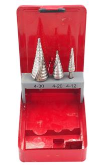
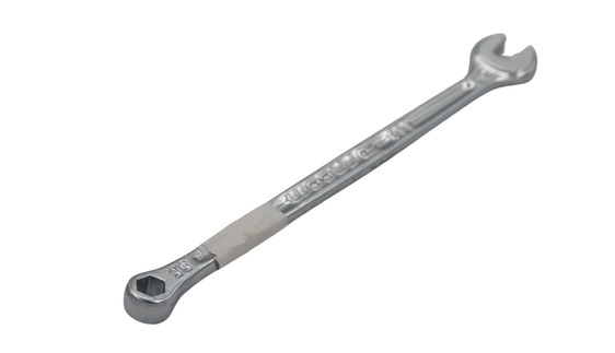
It will also be useful to have these tools:
|
|


Step 1: Electronic section assembly#
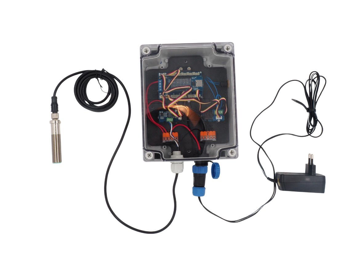
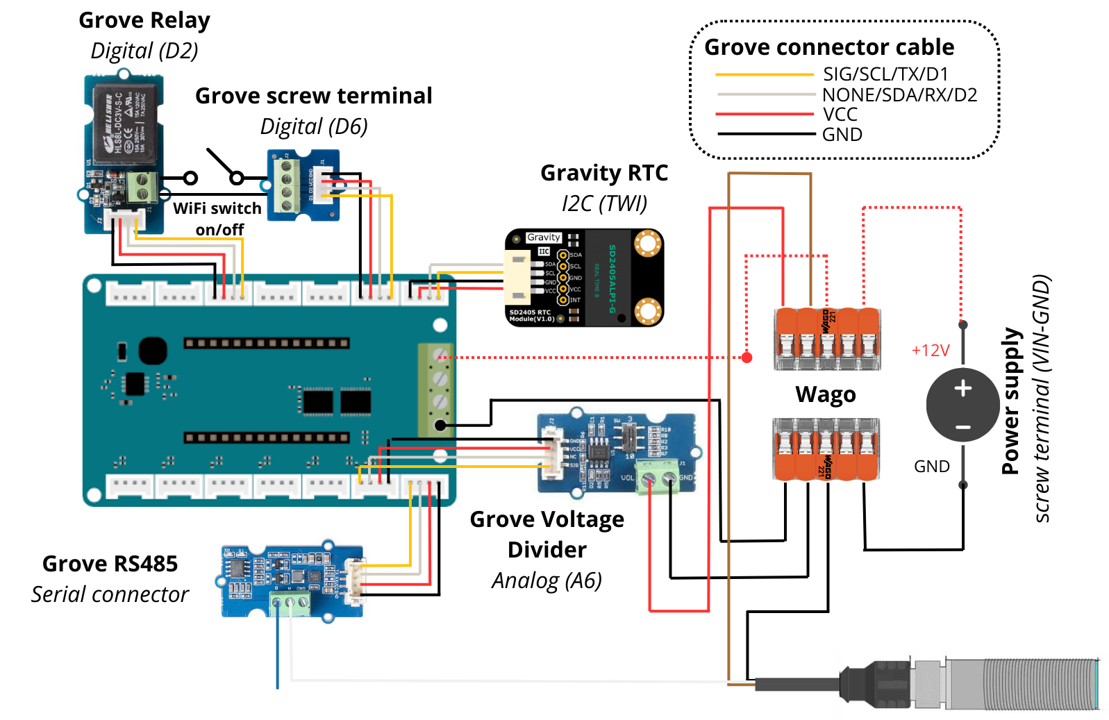
The first part consists of assembling the various electronic boards of the datalogger to obtain the wiring shown below.
Electronic schematic#
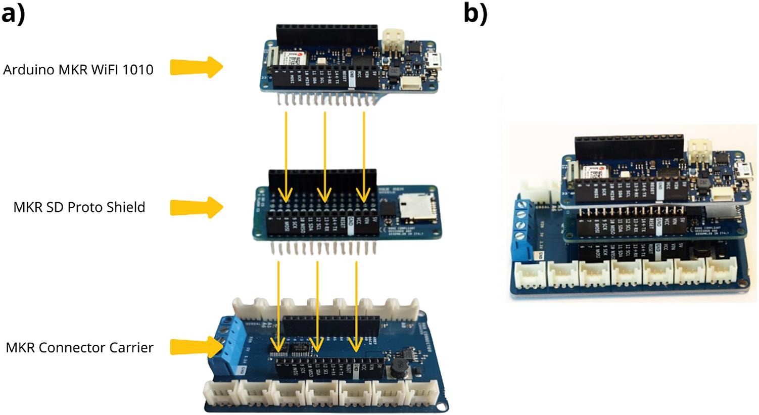
1. Assembly of Arduino MKR boards#
These boards control the datalogger’s components (sensor, button…) and record associated data (measurement, timestamp).
Insert the MKR MEM Shield onto the MKR Connector Carrier, then place the MKR WIFI 1010 onto the MKR MEM Shield.
The resulting configuration is shown below.
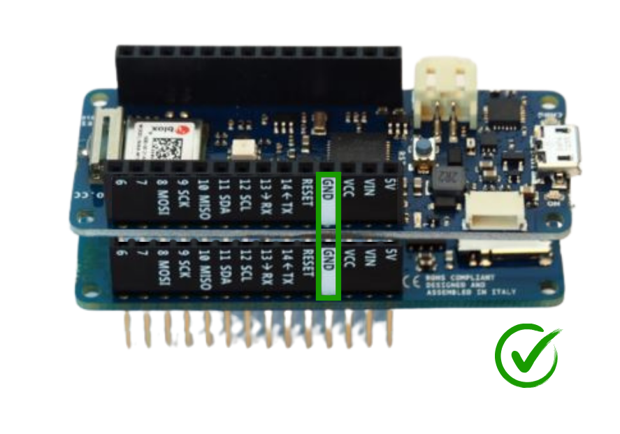
Attention
The three boards must be stacked properly (GND to GND, etc.).
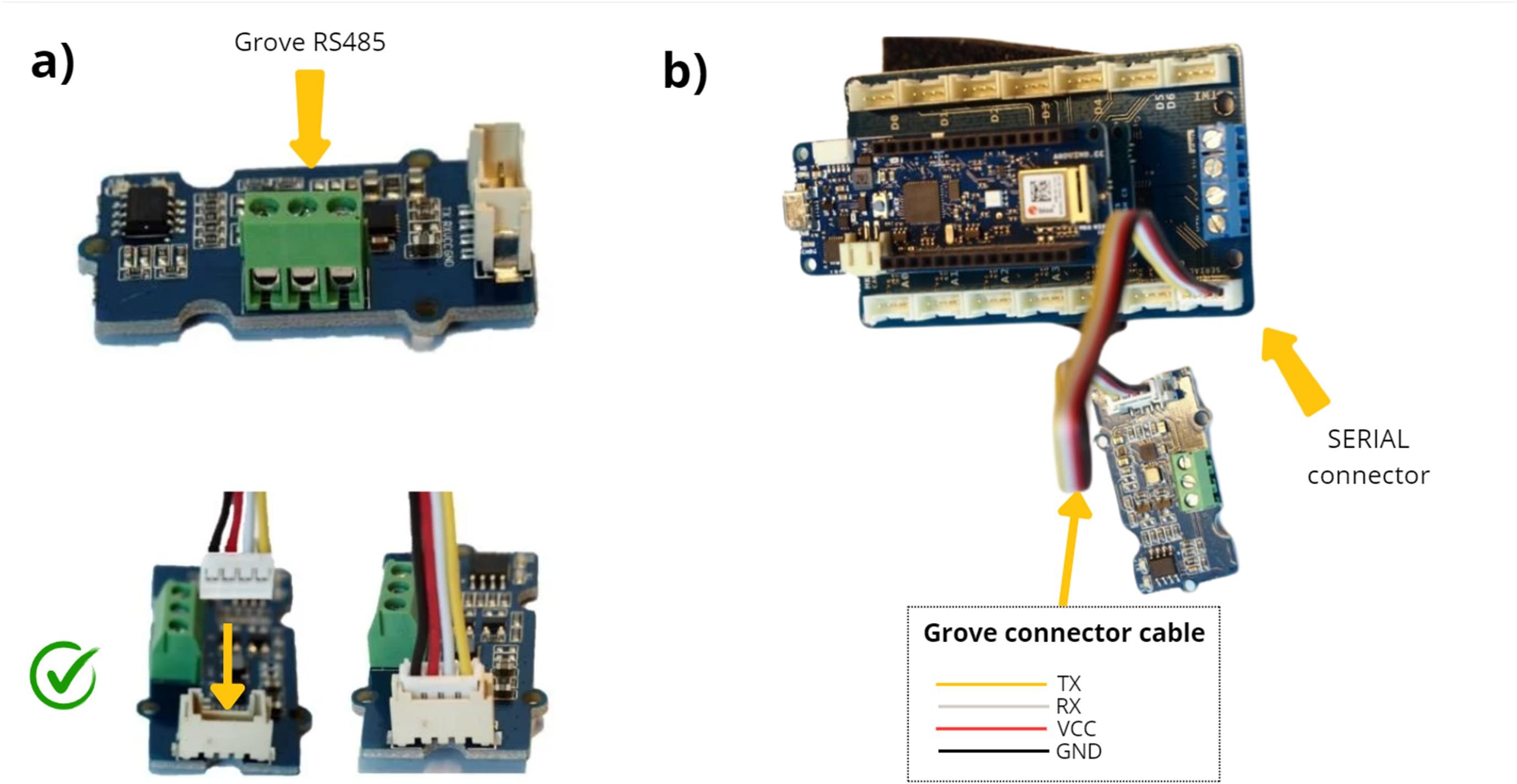
2. Connection of the RS485 communication module#
This module enables connection of an instrument or sensor using the RS485 communication protocol.
Take the Grove RS485 module and connect the supplied Grove connector cable.
Connect the other end of the cable from the RS485 module to the SERIAL port on the MKR CONNECTOR CARRIER board.
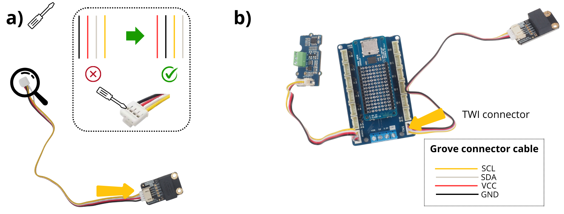
3. Connection of the Grove RTC module#
The Grove RTC module manages the timestamp of recorded data (RTC = Real Time Clock).
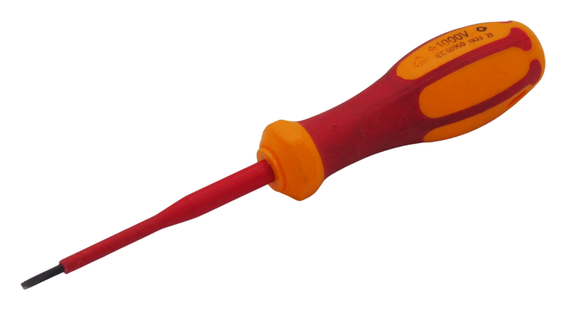
Take the Grove RTC board and connect the supplied Grove connector cable. Using a fine flat screwdriver, swap the red‑black pair and the white‑yellow pair on the opposite end.
See also
To understand cable inversion, see video: https://www.youtube.com/watch?v=0G7iIwfuaJ8
Connect the other end of the Grove RTC cable to the TWI port of the MKR CONNECTOR CARRIER board.
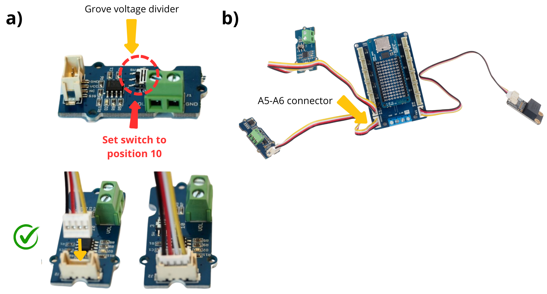
4. Wiring the :term`Module Grove Voltage Divider`.#
This module measures battery voltage; change the Switch for 12 V supply.
Take the voltage‑divider board and attach the supplied Grove connector cable. Move the switch from position 3 to 10.
Connect the other end of the voltage‑divider cable to the A5‑A6 port of the MKR CONNECTOR CARRIER board.
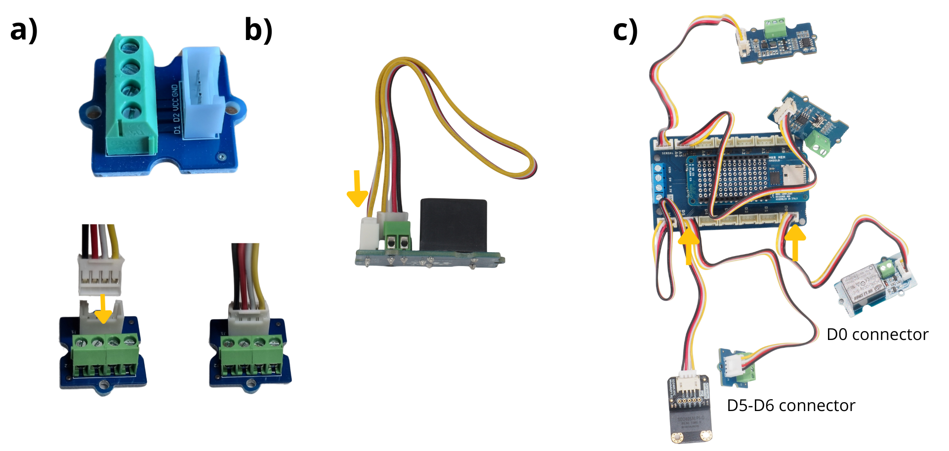
5. Connection of the Screw Terminal and Grove Relay modules#
The Grove Relay module controls the power supply of a component, acting as a switch. It drives the push‑button here. The Screw Terminal module provides wiring interfaces for components that the microcontroller will later manage, in this case the push‑button.
Take the Grove Screw Terminal module and connect the supplied Grove connector cable.
Take the Grove Relay module and connect the supplied Grove connector cable.
Connect the Grove Screw Terminal to port D5‑D6 and the Grove Relay to port D0.
Step 2: Mechanical assembly#
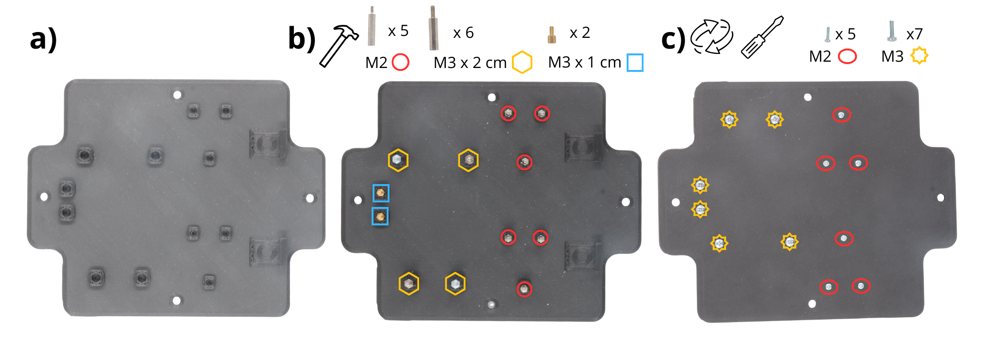
1. Preparation of the basket‑base support#
Details on using a printed board are provided here. If you lack a 3‑D printer, contact a local Fab‑lab.
Take the plate.
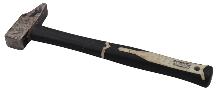
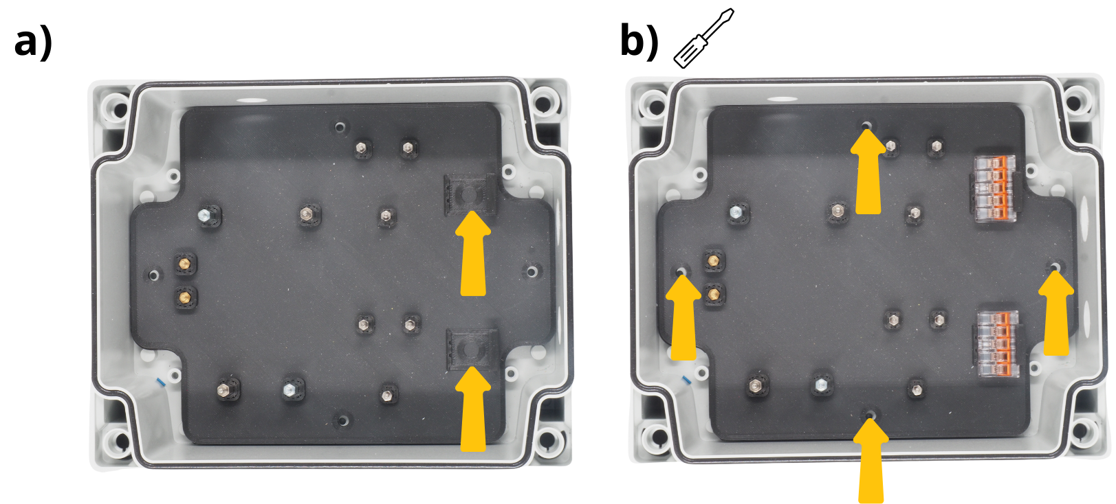
Insert the M2 spacers (2 cm), M3 spacers (2 cm) and M3 spacers (1 cm) into the designated holes. They may be placed in either orientation. Depending on the chosen orientation, later steps may require extra nuts or screws. A hammer can be used to seat them more deeply.
Flip the plate and insert the M2 screws and M3 screws into the designated holes to secure the spacers.
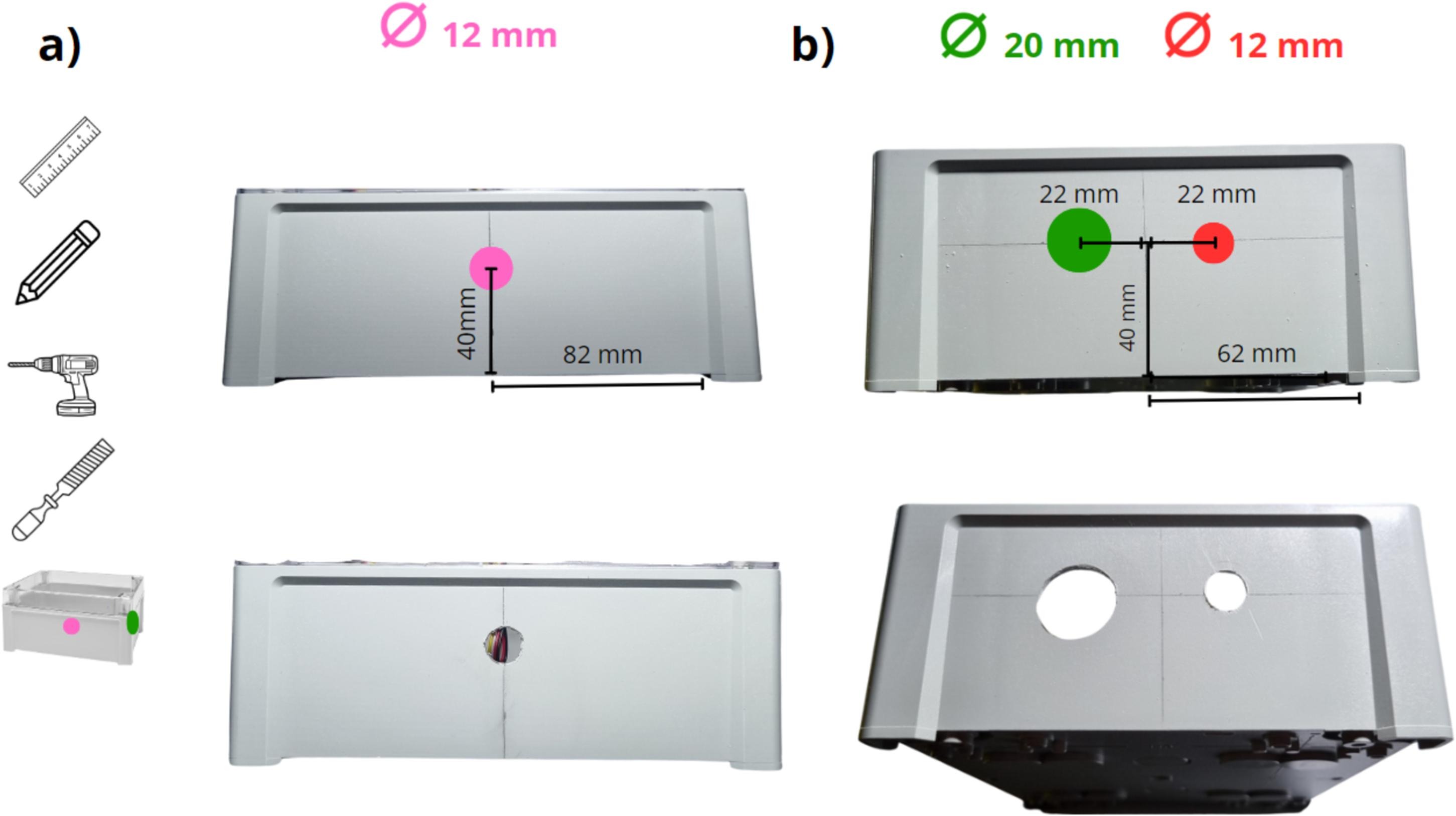
Take the enclosure, drill a 12 mm hole on the longer side (see below).
Take the enclosure, drill a 20 mm hole on the shorter side and a 12 mm hole (see below).
Place the plate inside the enclosure and insert the two WAGO connectors into the designated slots.
Secure the plate in the enclosure using the four supplied screws.
2. Placement and fixation of Arduino and Grove boards#
Note
For upcoming steps, screw components gently; no force required.
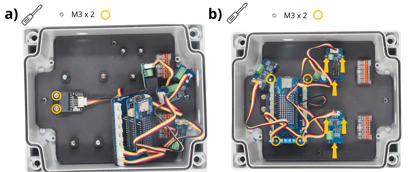
Secure the RTC board with M3 nuts onto the designated spacers.
Secure the Arduino stack with M3 nuts onto the designated spacers above the RTC board. Mount the Grove Voltage Divider and Grove Relay on the remaining M2 spacers.
3. Wiring power to Arduino boards#
Note
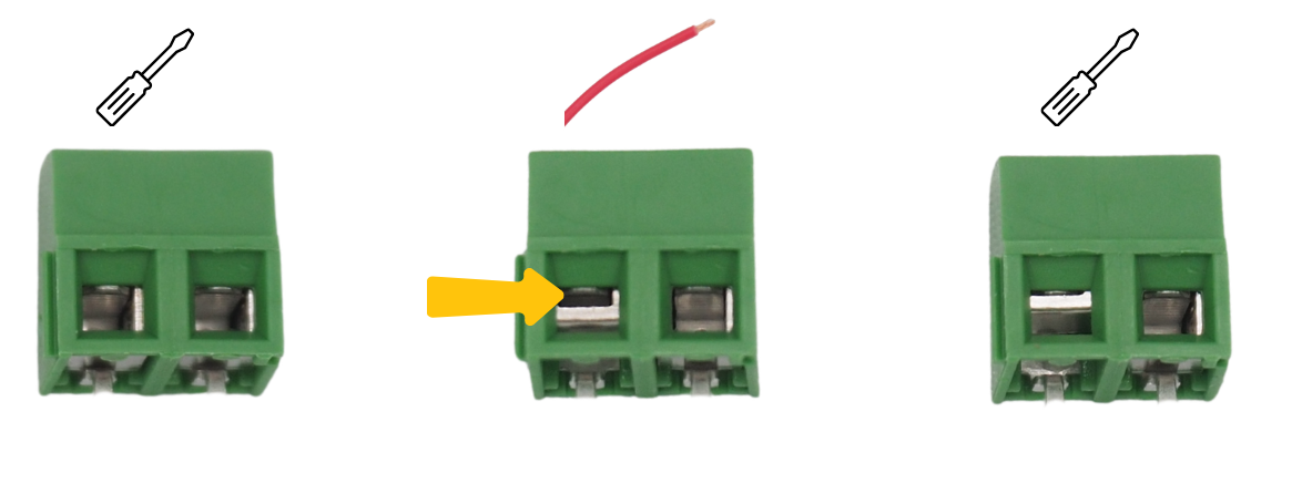
For subsequent steps, insert cables into different :term`Bornier à vis` and tighten. Prior to that, unscrew the :term`Bornier à vis` (see image), open it, insert the cable, then re‑screw to close the terminal around the cable.
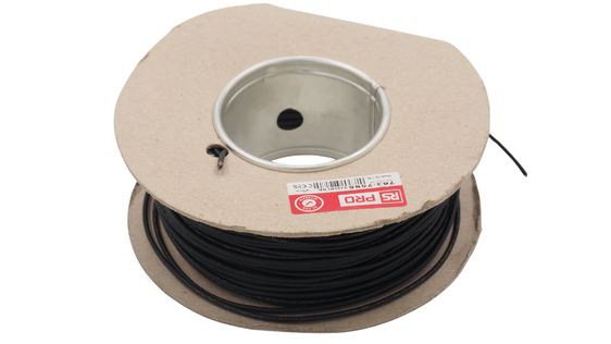
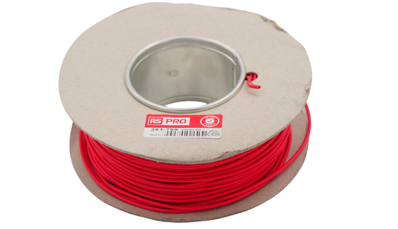
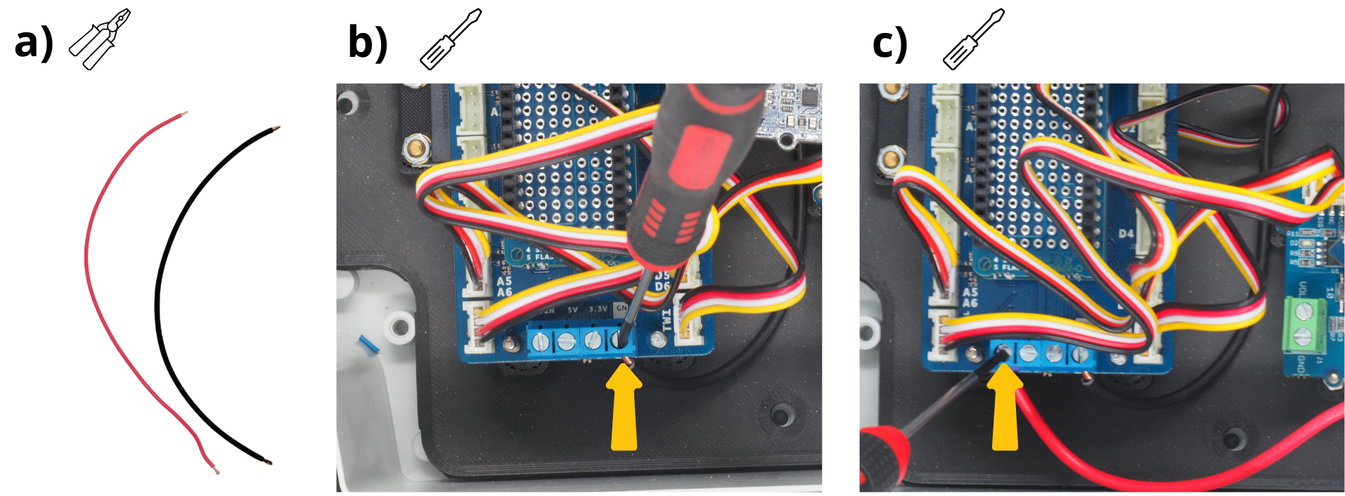
Cut and strip a 20 cm red and a 20 cm black wire.
Insert the black cable into the :term`Bornier à vis` GND of the :term`Arduino MKR Connector Carrier` and tighten.
Insert the red cable into the :term`Bornier à vis` VIN of the :term`Arduino MKR Connector Carrier` and tighten.
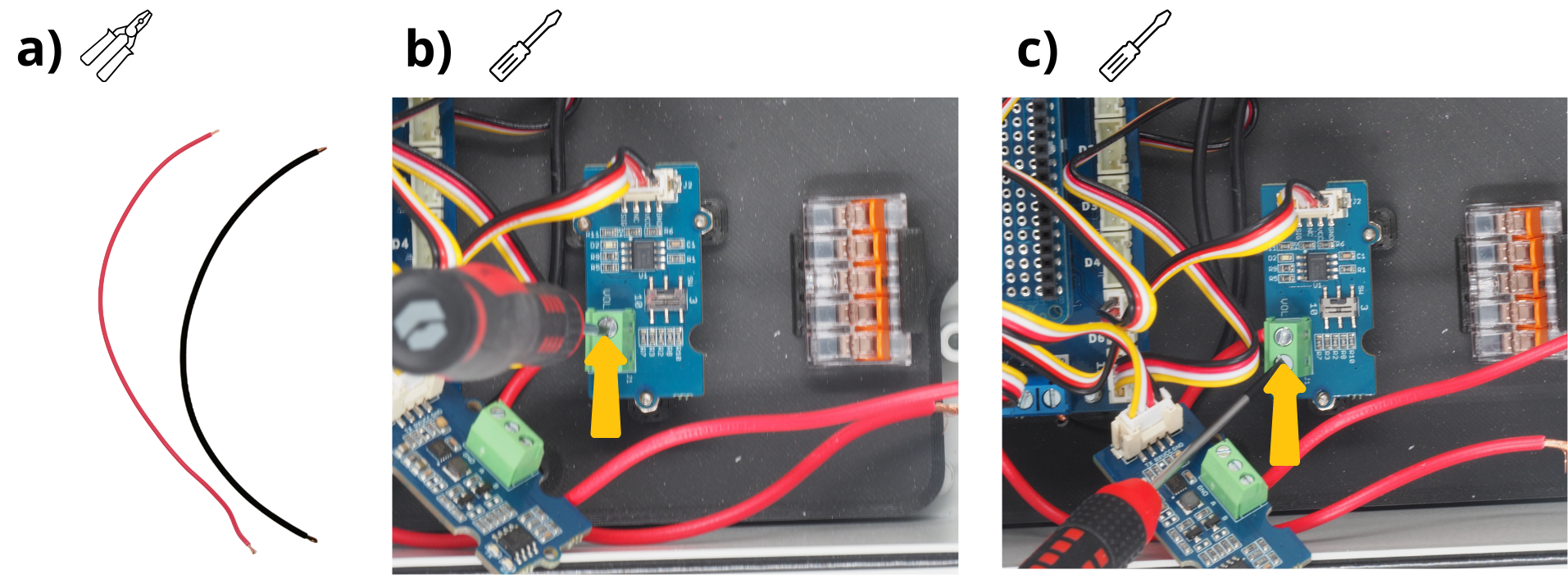
4. Wiring the :term`Module Grove Voltage Divider`.#
Note
For the following steps, you will regularly be asked to insert cables into different :term`Bornier à vis` and tighten them. First, you must unscrew the :term`Bornier à vis` (see image), open it, insert a cable, and then re‑screw to close the terminal around the cable.
Cut a 15 cm red wire and a 15 cm black wire, then strip their ends with a wire stripper.
Insert the red cable into the :term`Bornier à vis` VOL of the :term`Module Grove Voltage Divider` and tighten.
Insert the black cable into the :term`Bornier à vis` GND of the :term`Module Grove Voltage Divider` and tighten.
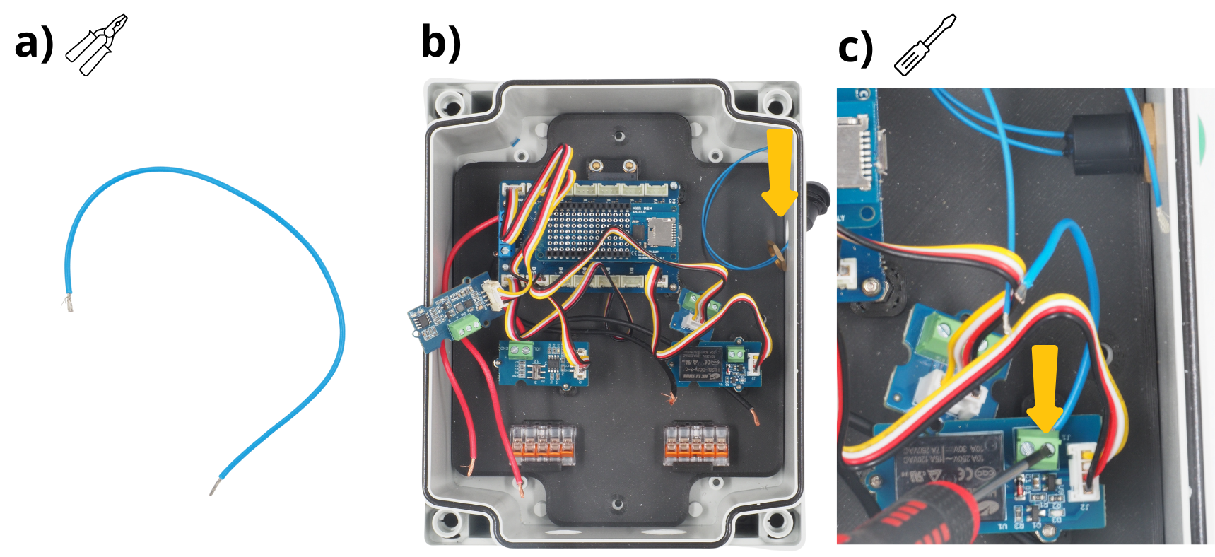
5. Wiring and fixing the push button.#
Cut a 10‑cm wire, strip its ends with a wire stripper. Wire colour is irrelevant.
Take the push button, strip the ends of its two wires, and insert them into the designated hole. Secure with the provided screw and gasket.
Insert one end of the blue wire into any port of the :term`Module Grove Relay` and tighten.
Attention
The push‑button gasket must be placed outside the box.
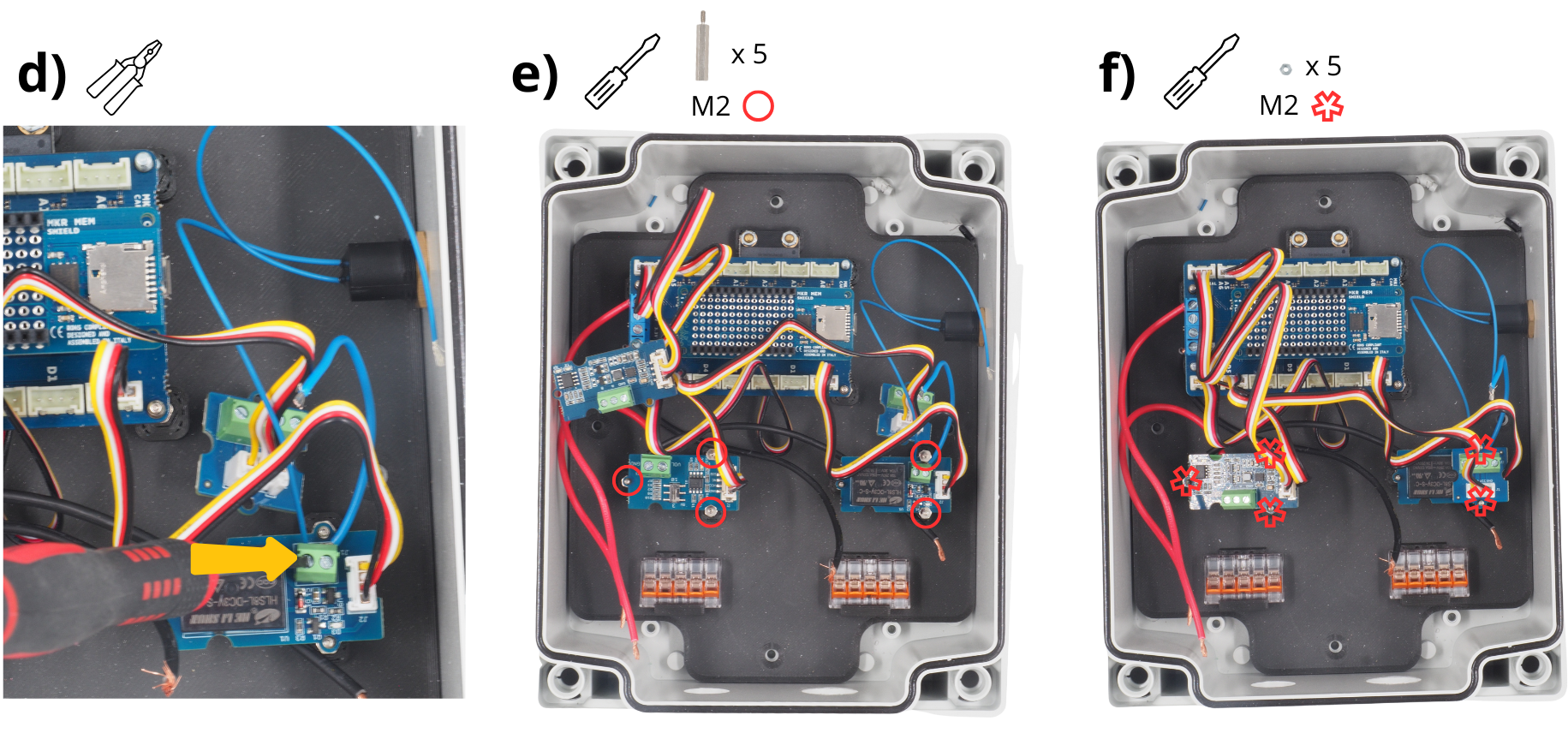
Insert one of the push‑button wires into the remaining :term`Module Grove Relay` port and tighten.
Secure the :term`Module Grove Voltage Divider` and :term`Module Grove Relay` using :term`Entretoise` M2.
Mount the :term`Module Grove RS485` on the :term`Entretoise` of the :term`Module Grove Voltage Divider`, and the :term`Module Grove Screw Terminal` on the :term`Entretoise` of the :term`Module Grove Relay`. Fasten with M2 nuts.
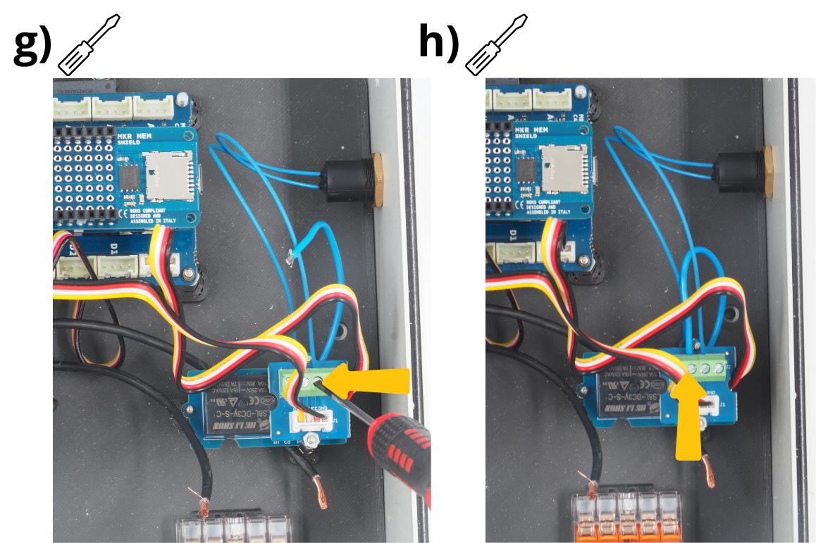
Insert the other push‑button wire into the VCC port of the :term`Module Grove Screw Terminal` and tighten.
Insert the remaining wire end into the D2 port of the :term`Module Grove Screw Terminal` and tighten.
6. Power supply for the :term`Centrale Setier` flow‑meter central unit.#
The next step is to wire the power block of the :term`Centrale Setier` central unit. This block must be connected to a 220 V outlet during use of the central unit.
Cut and strip a 20 cm red and a 20 cm black wire.
Take the traversing panel power connector.
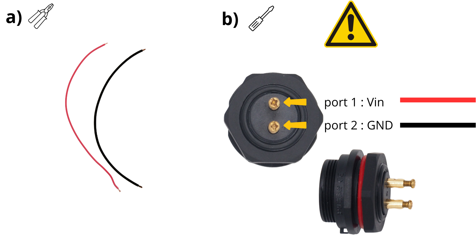
Insert one end of the red cable into the :term`Bornier à vis` “1” of the traversing panel power connector and tighten.
Insert one end of the black cable into the :term`Bornier à vis` “2” of the traversing panel power connector and tighten.
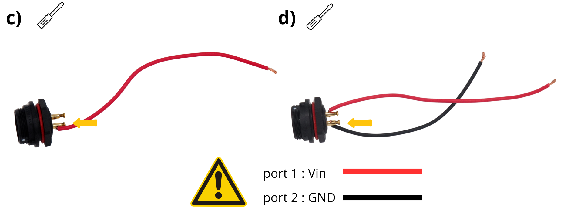
Attention
Use a heat‑shrink tube to prevent GND‑VIN short.
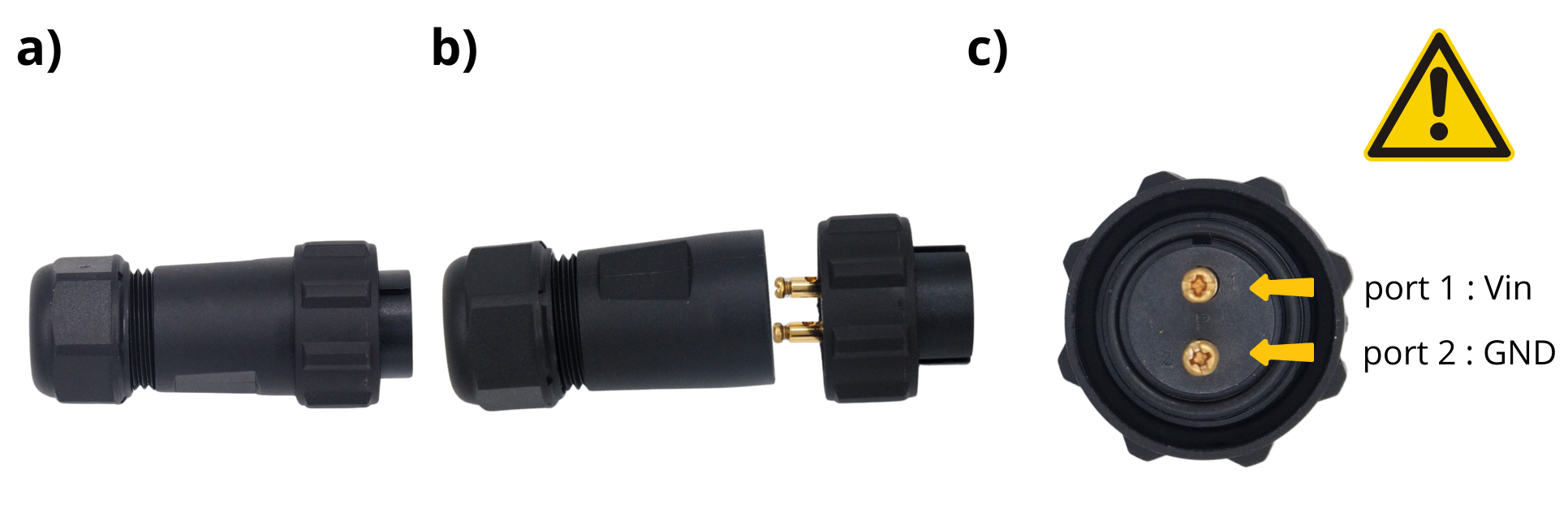
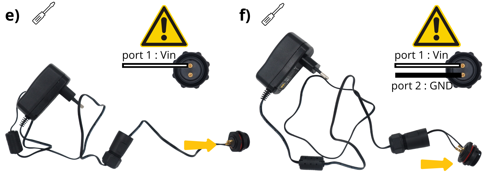
Take the panel power connector.
Unscrew to access the connection screws.
Observe the markings around it (port 1 and port 2).
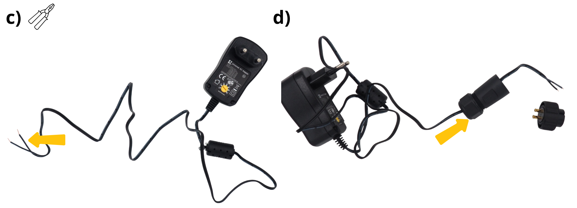
Take the 220 V–12 V power supply, flip it, and use a screwdriver to set its output to 12 V.
Cut the end of this power supply.
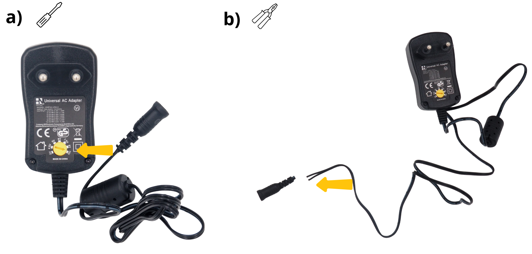
Strip the two wires at this end.
Pass the outer section of the power connector through the pressure‑seal.
Insert the white cable into the :term`Bornier à vis` “1” of the panel power connector. Ensure correct cable to correct terminal.
Insert the black cable into the :term`Bornier à vis` “2” of the panel power connector. Ensure correct cable to correct terminal.
Screw the :term`Presse‑étoupe` onto the previously connected connector.
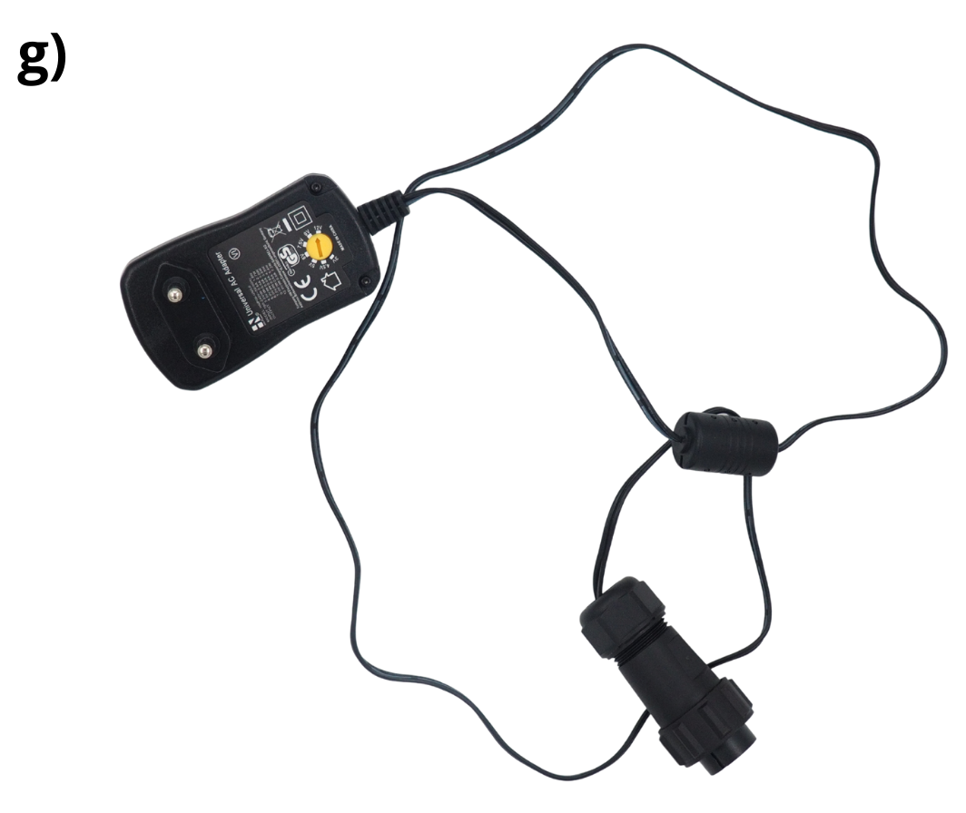
The power block is now ready. Insert the :term`Centrale Setier` power block into its cavity and secure with the supplied nut.
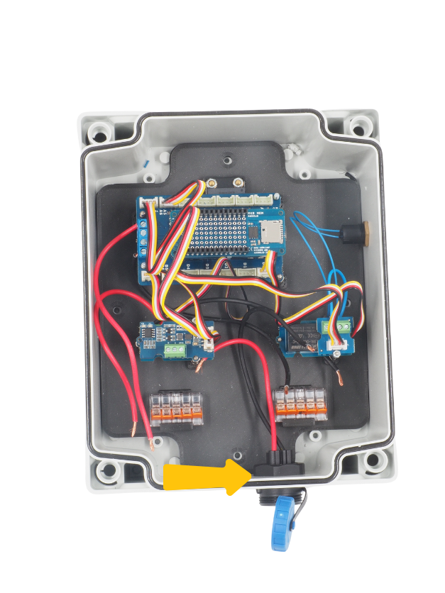
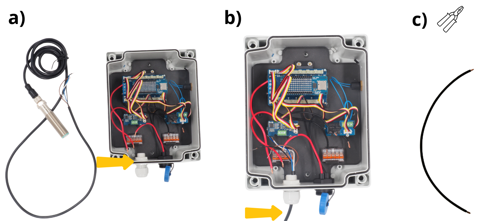
7. Wiring the SEN0358 sensor.#
Install the :term`Presse‑étoupe` M16 in the designated hole and unscrew the outer side.
Route the SEN0358 cable through the :term`Presse‑étoupe` and tighten the fitting with the unscrewed end.
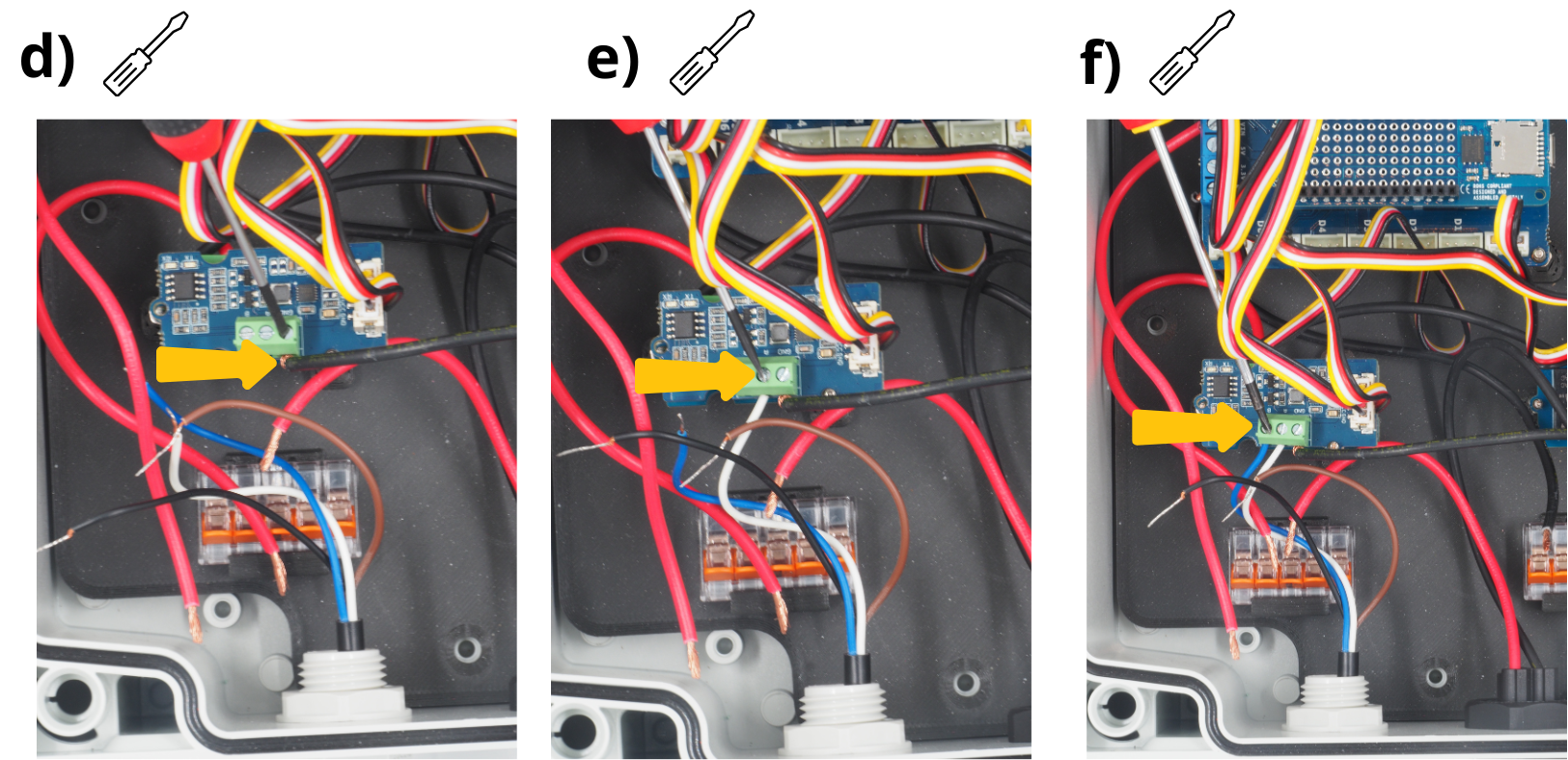
Cut a 15 cm black wire and strip both ends.
Insert the black cable end into the GND screw terminal of the :term`Module Grove RS485` and tighten.
Insert the white cable end from the sensor into the A terminal of the :term`Bornier à vis` module :term`Module Grove RS485` and tighten.
Insert the blue cable end from the sensor into the B terminal of the :term`Bornier à vis` module :term`Module Grove RS485` and tighten.
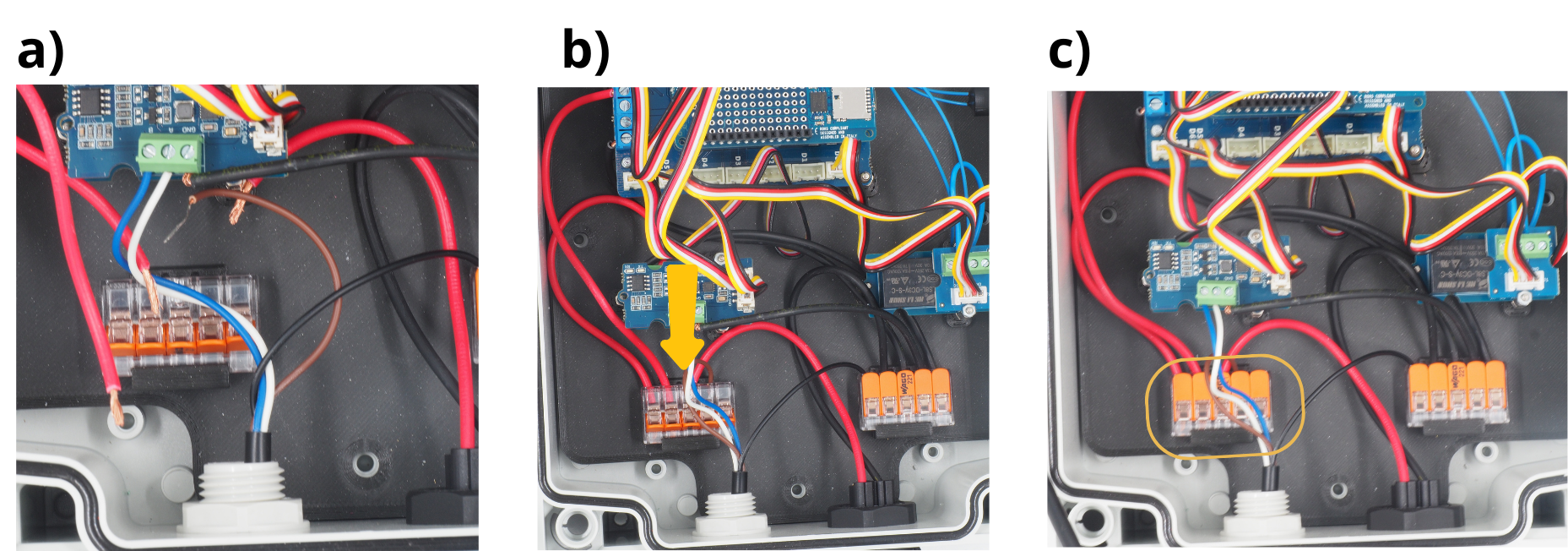
8. Ground (GND) wiring of all elements to a :term`Borne de connexion WAGO`.#
Open the five levers of the first :term`Borne de connexion WAGO`.
Insert the remaining black wire ends from the :term`Module Grove RS485`, the SEN0358 sensor, the :term`Module Grove Voltage Divider`, the power block, and from the card :term`Arduino MKR Connector Carrier`.
Close the five levers of the :term`Borne de connexion WAGO`.
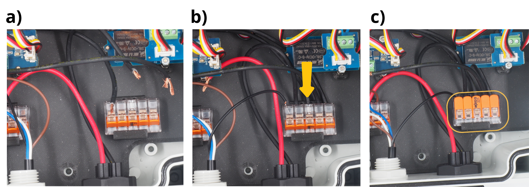
9. Wiring the 12 V supply of all components to a :term`Borne de connexion WAGO`.#
Open the four levers of the first :term`Borne de connexion WAGO`.
Insert the remaining red‑wire ends into each lever: from the SEN0358 sensor, the :term`Module Grove Voltage Divider`, the panel power connector, and from the card :term`Arduino MKR Connector Carrier`.
Close the four engaged levers of the :term`Borne de connexion WAGO`.
11. Closing the Enclosure and powering the :term`Boitier`.#
Take the box and place its lid on top.
Close the box by screwing the lid with the four supplied screws.
Take the central unit power plug and connect it to the power block.
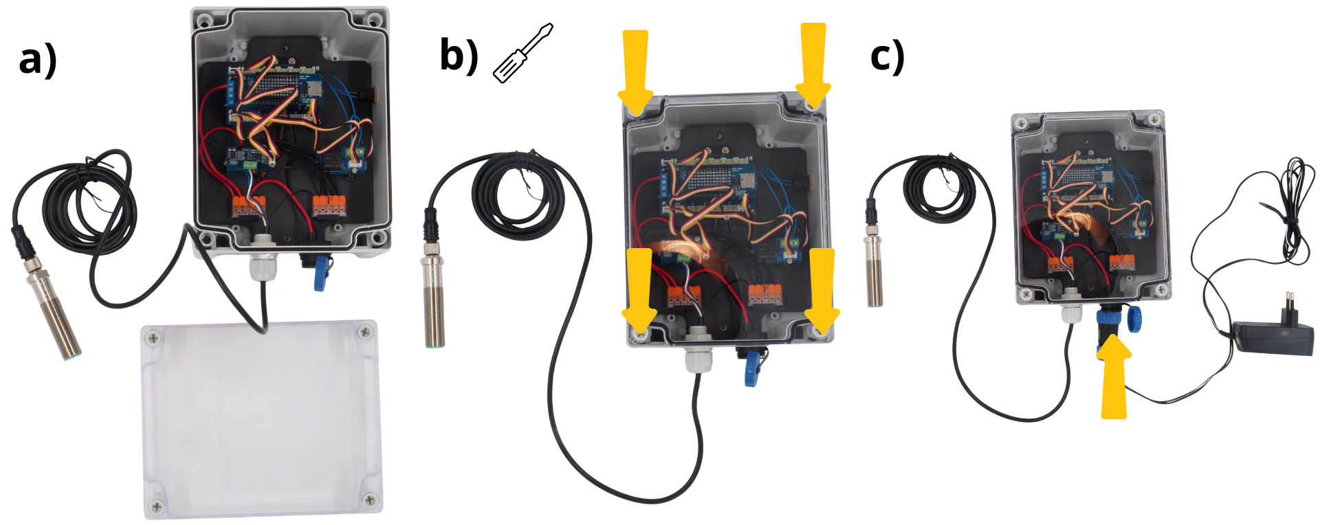
The :term`Centrale Setier` flow‑meter central unit is ready for programming and subsequent use.