Energy#
Installation instructions
Please refer to this document for instructions on how to assemble the SETIER Energie system. As of 9 February 2026, the cost of the materials required for assembly is €338.88 (for a system with 2 panels). It takes 6 hours to assemble and programme this system. For this assembly, we recommend that you work in a well-lit, quiet room, as some steps may require precision. Ensure you have all the necessary materials and tools before beginning the assembly. The lists of tools and materials are provided later in this documentation.Please refer to this document to assemble the Energy datalogger V1.02 associated with the SETIER project.
Informations
SETIER is an open collaborative project. However, assembling the associated dataloggers requires compliance with safety rules for electronic board usage. SETIER dataloggers must be assembled in a professional setting by personnel with electronics expertise. The SETIER team is not liable for any material or personal damage that may occur during assembly or use of a SETIER datalogger. Moreover, the SETIER team cannot be held responsible if the datalogger fails after assembly. You may redistribute and modify this documentation and create products using it under the CERN-OHL-P v2 terms (https://cern.ch/cern-ohl). This documentation is provided WITHOUT ANY EXPRESS OR IMPLIED WARRANTY, INCLUDING MERCHANTABILITY, SATISFACTORY QUALITY AND FITNESS FOR A PARTICULAR PURPOSE. See the CERN-OHL-P v2 for conditions.
You may redistribute and modify this documentation and make products using it under the terms of the CERN-OHL-P v2 (https:/cern.ch/cern-ohl). This documentation is distributed WITHOUT ANY EXPRESS OR IMPLIED WARRANTY, INCLUDING OF MERCHANTABILITY, SATISFACTORY QUALITY AND FITNESS FOR A PARTICULAR PURPOSE. Please see the CERN-OHL-P v2 for applicable conditions.
Technical Data#
Data representing the various parameters associated with the operation of the Energy plant.
Parameters |
Specifications |
Units |
Input voltage (VCC) |
3.3 to 5.5 |
V |
Measurement range |
0 to 5, 10 or 20 |
A |
Measurement accuracy |
±1% |
% |
Non-linearity |
±0.2 |
% |
Cable length |
1 |
m |
Operating temperature |
-25 to 70 |
°C |
Opening size (L×l) |
13×13 |
mm |
Data storage |
micro SD card |
Matériel nécessaire#
Afin d’assembler la Centrale Setier Energie, le matériel nécessaire est le suivant :
Bill of Materials:
Component |
Number |
Cost per unit € |
Total cost € |
Manufacturer |
Ref. manufacturer |
Web reference |
|---|---|---|---|---|---|---|
Arduino MKR Wifi 1010 |
1 |
33.61 |
33.61 |
Arduino |
782-ABX00023 |
https://www.mouser.fr/ProductDetail/Arduino/ABX00023?qs=%252BEew9%252B0nqrAwxv2YQYWyPw%3D%3D |
Arduino MEM Shield |
1 |
19.55 |
19.55 |
Arduino |
782-ASX00008 |
https://www.mouser.fr/ProductDetail/Arduino/ASX00008?qs=%252BEew9%252B0nqrB6JgKBlp7dtg%3D%3D |
Arduino MKR Connector Carrier |
1 |
19.4 |
19.4 |
Arduino |
782-ASX00007 |
https://www.mouser.fr/ProductDetail/Arduino/ASX00007?qs=%252BEew9%252B0nqrD3EEw%252BoCBXVA%3D%3D |
Gravity RTC |
1 |
7.4 |
7.4 |
DFRobot |
426-DFR0469 |
https://www.mouser.fr/ProductDetail/DFRobot/DFR0469?qs=EU6FO9ffTwe22wh0PfInCA%3D%3D |
Grove Voltage divider |
1 |
5.55 |
5.55 |
Seeed-Studio |
104020000 |
https://fr.farnell.com/seeed-studio/104020000/voltage-divider-board-arduino/dp/4007781?ost=104020000 |
Grove I2C Hub |
1 |
2.79 |
2.79 |
Seeed-Studio |
103020006 |
https://www.mouser.fr/ProductDetail/Seeed-Studio/103020006?qs=1%252B9yuXKSi8ASpEzkjFrVZQ%3D%3D |
Grove 4 Channel SPDT Relay |
1 |
13×13 |
13×13 |
Seeed-Studio |
103020133 |
https://www.mouser.fr/ProductDetail/Seeed-Studio/103020133?qs=MLItCLRbWsy5SaEtoXFpug%3D%3D |
Grove 4 pin Conversion cable |
5 |
2.88 |
2.88 |
Seeed-Studio |
110990210 |
https://www.mouser.fr/ProductDetail/Seeed-Studio/110990210?qs=1%252B9yuXKSi8A2O44lPDM%252BLw%3D%3D |
Jumper Wire |
50 |
13.46 |
13.46 |
OSEPP-Electronic |
LS-MMPJ-6 |
https://www.mouser.fr/ProductDetail/OSEPP-Electronics/LS-MMPJ-6?qs=wNBL%252BABd93OjwYkdMfv4tA%3D%3D |
Spacer M2x2cm |
1 |
0.808 |
8.08 |
Wurth-Elektronik |
710-971200244 |
https://www.mouser.fr/ProductDetail/Wurth-Elektronik/971200244?qs=wr8lucFkNMW86Ww6MhRnZQ%3D%3D |
Spacer M3x2cm |
1 |
1.08 |
10.8 |
Wurth-Elektronik |
710-971200354 |
https://www.mouser.fr/ProductDetail/Wurth-Elektronik/971200354?qs=wr8lucFkNMXVQ0nS%2FAg5sw%3D%3D |
Screw M2x8mm |
20 |
4.48 |
4.48 |
RS-PRO |
908-7637 |
|
Screw M3x8mm |
20 |
4.28 |
4.28 |
RS-PRO |
908-7661 |
|
Nut M3 |
20 |
8.18 |
8.18 |
Wurth-Elektronik |
560-293 |
|
Nut M2 |
20 |
7.41 |
7.41 |
Wurth-Elektronik |
560-271 |
|
Box Polycarbonate 344x289x117mm IP65 |
1 |
93.68 |
93.68 |
RS-PRO |
197-2020 |
https://fr.rs-online.com/web/p/boitiers-pour-usage-general/1972020?gb=a |
Pushbutton |
1 |
8.5 |
8.5 |
ITW Switches |
265-0635 |
|
Grove Screw Terminal |
1 |
1.9 |
1.9 |
Seeed-Studio |
713-103020007 |
https://www.mouser.fr/ProductDetail/Seeed-Studio/103020007?qs=1%252B9yuXKSi8B56dS97ffOlA%3D%3D |
Gravity Analog AC Current Sensor 20 A SEN0211 |
1 |
17.11 |
17.11 |
DFRobot |
426-SEN0211 |
https://www.mouser.fr/ProductDetail/DFRobot/SEN0211?qs=lqAf%2FiVYw9hjsLDR5pIEyg%3D%3D |
Gravity Analog AC Current Sensor 10 A SEN0288 |
1 |
17.11 |
17.11 |
DFRobot |
426-SEN0288 |
https://www.mouser.fr/ProductDetail/DFRobot/SEN0288?qs=wnTfsH77Xs5CJ1ZxrmDBOA%3D%3D |
Gravity Analog AC Current Sensor 5 A SEN0287 |
1 |
17.11 |
17.11 |
DFRobot |
426-SEN0287 |
https://www.mouser.fr/ProductDetail/DFRobot/SEN0287?qs=wnTfsH77Xs4%252BGDLhfV%2FyWQ%3D%3D |
Female panel connector IP68 21mm 2 contacts |
1 |
19.3 |
19.3 |
RS-PRO |
124-6674 |
https://fr.rs-online.com/web/p/connecteurs-circulaires-industriels/1246674?gb=a |
Male cable connector IP68 21mm 2 contacts |
1 |
21.89 |
21.89 |
RS-PRO |
124-6683 |
|
AC/DC 3V Adaptator |
1 |
12.75 |
12.75 |
RS-PRO |
206-4908 |
|
WAGO 221 3 levers |
1 |
9.57 |
9.57 |
WAGO |
221-423 |
https://fr.rs-online.com/web/p/borniers-de-raccordement/2825143 |
PVC panel |
1 |
1 |
3D Print |
|||
Cable gland |
1 |
15.1 |
15.1 |
RS-PRO |
822-9653 |
|
Micro SD card |
1 |
12.09 |
12.09 |
SanDisk |
467-SDSDQAB-016G |
https://www.mouser.fr/ProductDetail/SanDisk/SDSDQAB-016G?qs=EgF7oUuTQmp8cNxoHCNycQ%3D%3D |
USB µUSB connector |
1 |
2.19 |
2.19 |
Qualtek |
562-3025033-01 |
https://www.mouser.fr/ProductDetail/Qualtek/3025033-01?qs=1mbolxNpo8c5JqM9YiGl1Q%3D%3D |
Pressure compensation |
1 |
18.50 |
18.5 |
Schneider Electric |
177-8973 |
Tools required#
You will also find it useful to have the following tools:
|
|


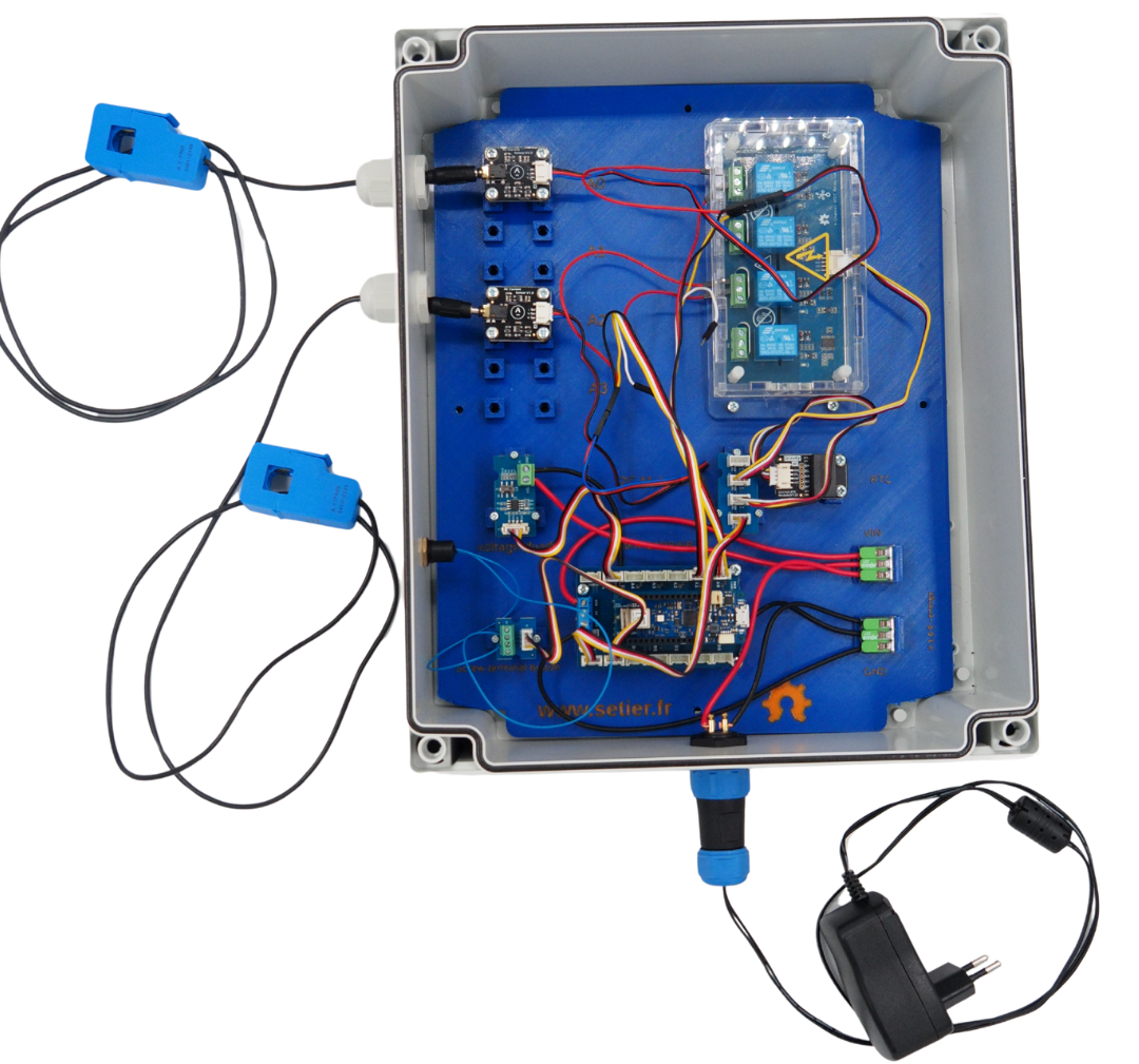
This installation guide explains how to install an energy data logger with two current sensors, but it is possible to connect up to four. For details on how to do this, please refer to the notes in the sections covering the connection of these sensors.
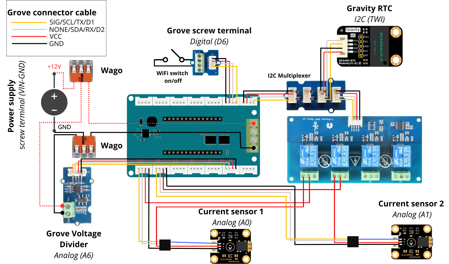
Electrical Diagram#
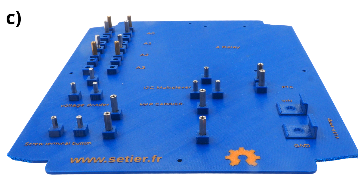
Step 1: Preparing the backplane#
1. Fitting the Entretoise#
This section explains how to use a printed plate. If you don’t have a 3D printer, please contact a Fablab near you.
Take the plate.
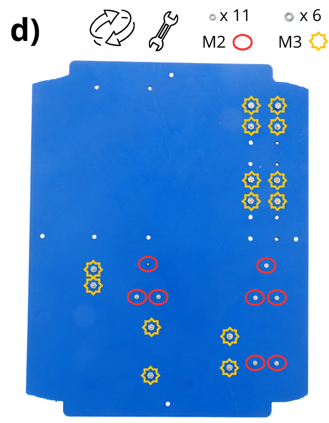
Insert the Entretoise 1.6 cm M2, 2 cm M3 spacers and 1 cm M3 spacers into the holes provided. You can use a hammer to drive them in further.
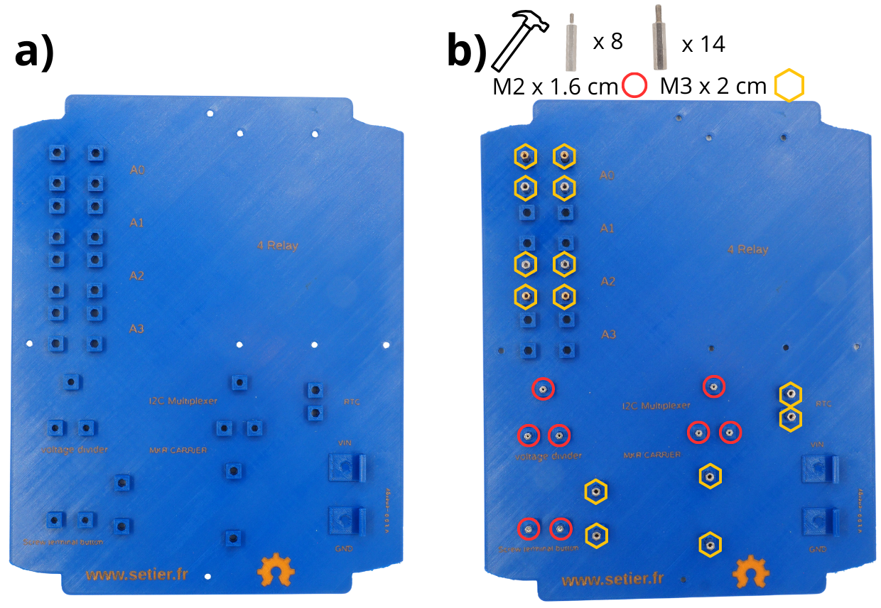
Attention
For the rest of the assembly, the female end of the Entretoise must face upwards.
Another view of the result after the Entretoise have been fitted.
Then turn the plate over. Next, using M2 and M3 nuts, secure the **M2 and M3 Entretoise that were previously inserted into the various holes.
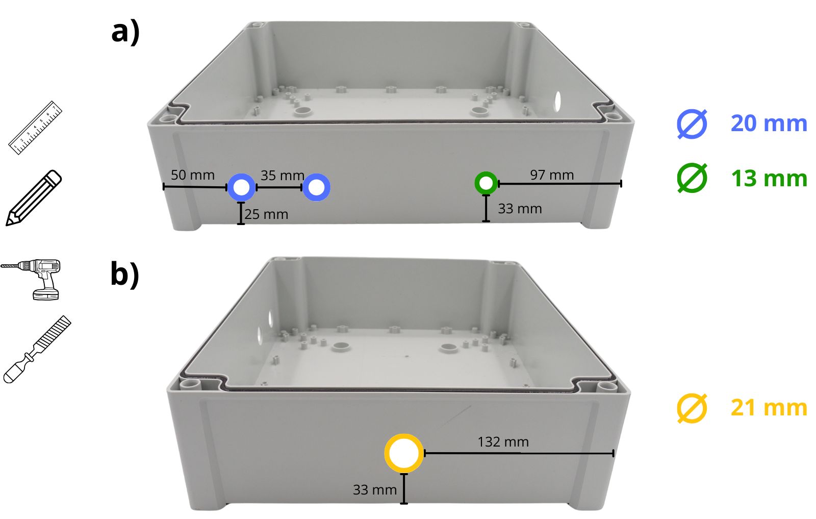
Take the box and drill a 20 mm diameter hole for each sensor on the longest side (see instructions below), as well as a 13 mm diameter hole for the push button.
Take the box and drill a 21 mm diameter hole in the shorter side, as well as a 12 mm diameter hole (see diagram below).
2. Installation of WAGO connection terminals#
Take the plate.
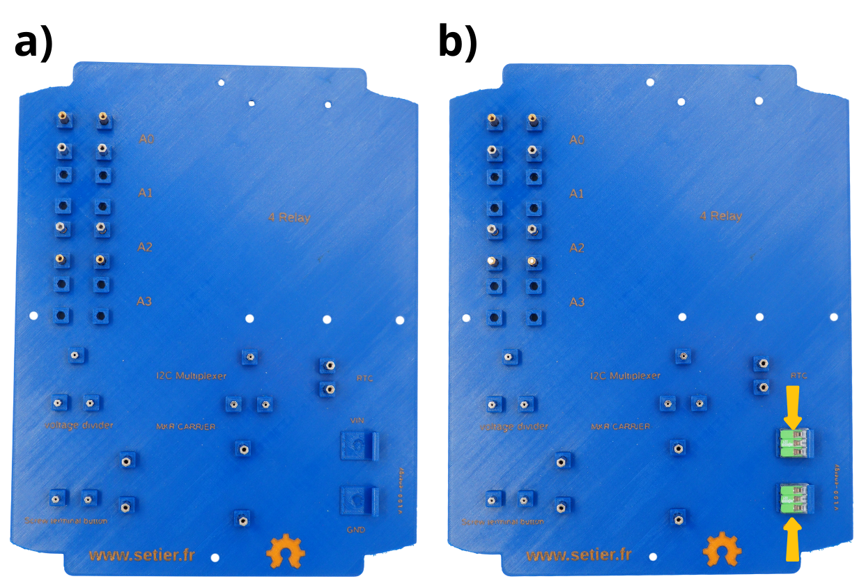
Insert the WAGO terminal blocks into the designated holders. To do this, simply slide them into place.
Step 2: Assembling and installing the circuit boards#
1. Assembling and setting up Arduino MKR boards#
Note
In the following steps, you will regularly be asked to secure the various components by screwing them in place. Do not use excessive force when tightening the screws.
These cards enable the control of various devices connected to the Datalogger (sensors, buttons, etc.) as well as the recording of associated data (measurements, dates, etc.).
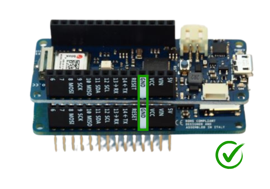
Insert the Arduino MKR MEM Shield onto the Arduino MKR Connector Carrier, then insert the Arduino MKR Wifi 1010 onto the Arduino MKR MEM Shield.
The result is as follows. Then insert the SD card into the designated slot on the Arduino MKR MEM Shield.
Place this Stack onto the M3 spacer provided for this purpose (labelled MKR CARRIER on the plate). Secure it using M3 screws.

Attention
The three circuit boards must be stacked in the correct orientation (e.g. GND pin to GND pin).
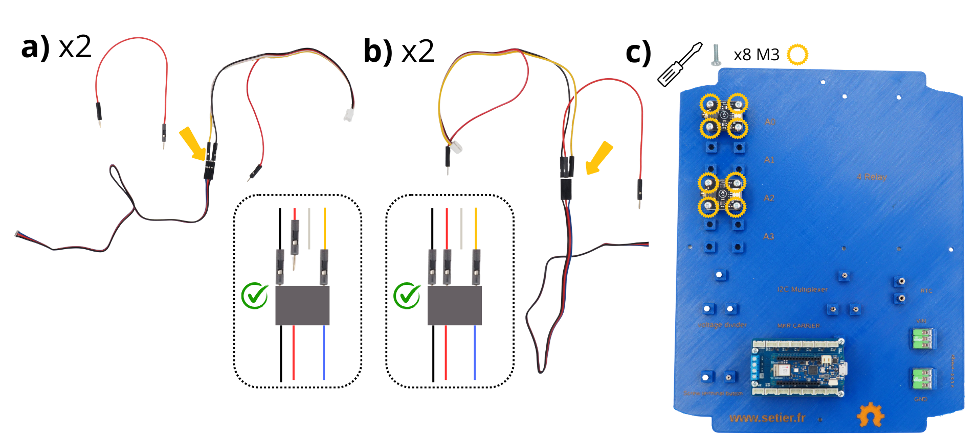
2. Assembly and installation of sensor measurement modules#
These modules enable the connection of sensors. They convert the sensor’s measurement signal, allowing it to be read via the Arduino boards connected to them.
Take the Measurement Module associated with each sensor, along with a red Picot cable and a Grove Picot cable. Connect the cable from the Measurement Module. Connect the yellow wire of the Grove Picot cable to the blue wire of the Measurement Module. Connect the black wire of the Grove Picot cable to the black wire of the Measurement Module.
Take the red Picot cable and connect one end to the measurement module. The other end will be connected later.
Place the two measurement modules on the M3 spacers provided for this purpose (labelled A0, A1, A2 and A3 on the plate, depending on the number of sensors to be connected). Secure them using M3 screws
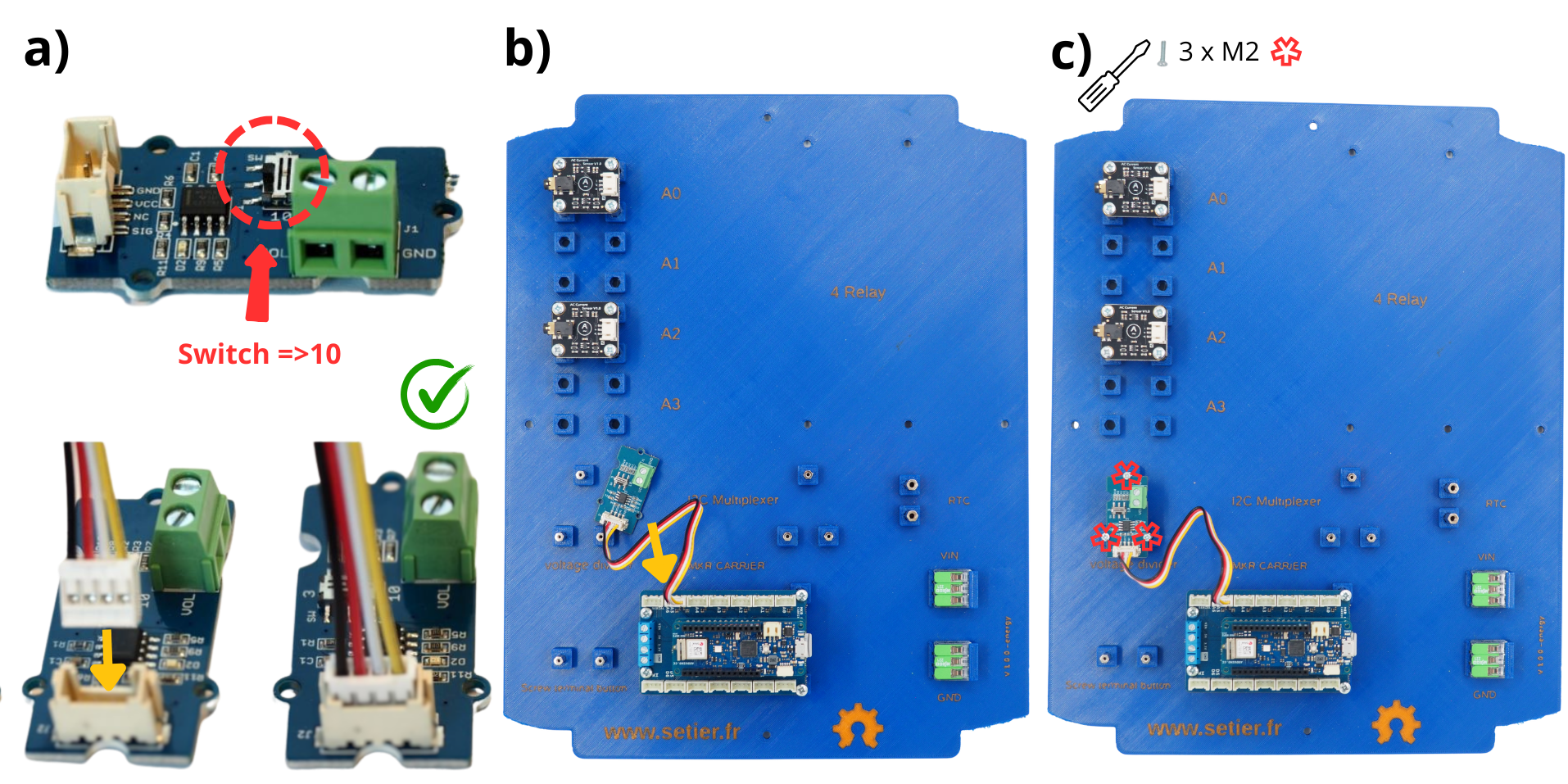
3. Assembling and installing the Grove Voltage Divider Module#
This module measures the system’s battery voltage. Because the system is powered from 12 V, the position of the switch must be adjusted accordingly.
Prendre le Module Grove Voltage Divider et brancher le câble Connecteur Grove fourni avec. Passer la position du commutateur de 3 à 10 (nommé Switch sur l’image).
Connect opposite end of the Grove cable to the A5‑A6 port on the MKR CONNECTOR CARRIER board.
Place the Grove Voltage Divider Module onto the :term:`M2** spacers** provided for this purpose (labelled voltage divider on the plate). Secure it using M2 screws.
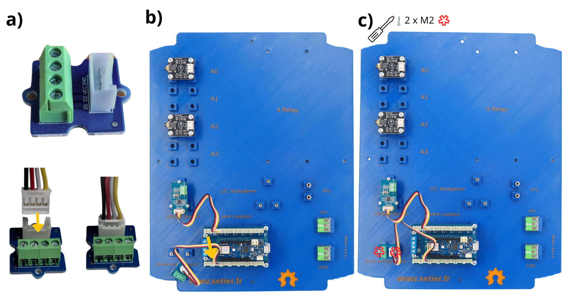
4. Assembling and installing the Grove Screw Terminal Module#
The Grove Screw Terminal Module allows you to connect various components via cables, which are then controlled by the microcontroller. In this case, it is used to connect the push-button.
Take the Grove Screw Terminal Module and connect the Grove Connector cable supplied with it.
Connect the other end of the cable Grove connector to the ‘D5-D6’ port on the Arduino MKR Connector Carrier board.
Place the Grove Screw Terminal Module onto the **M2** spacer provided for this purpose (labelled screw terminal button on the plate). Secure it using M2 screws.
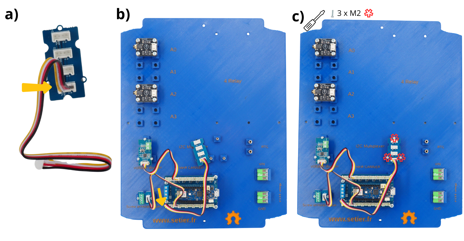
5. Assembling and installing the :term:` Grove I2C Multiplexer Module`#
The Grove I2C Multiplexer Module enables the interfacing of various systems that use I2C as their communication protocol.
Take the Grove I2C Multiplexer Module and connect the Grove Connector cable supplied with it.
Connect the other end of the cable:term:Grove connector to the ‘TWI’ port on the Arduino MKR Connector Carrier board.
Place the Grove I2C Multiplexer Module onto the **M2** spacer provided for this purpose (labelled I2C Multiplexer on the plate). Secure it using M2 screws.
6. Assembly and installation of the Gravity RTC Module#
The Gravity RTC Module manages the timing of the recorded data (RTC = Real Time Clock).
Take the Gravity RTC Module and connect the Grove connector cable supplied with it. At the other end of the cable, use a thin flat-bladed screwdriver to swap the red and black wires, as well as the white wire (see video).
Connect the other end of the cable:term:Grove connector to one of the available ports on the Grove I2C Multiplexer Module.
Place the Gravity RTC module onto the spacer M3 provided for this purpose (labelled RTC on the plate). Secure it using M3 screws.
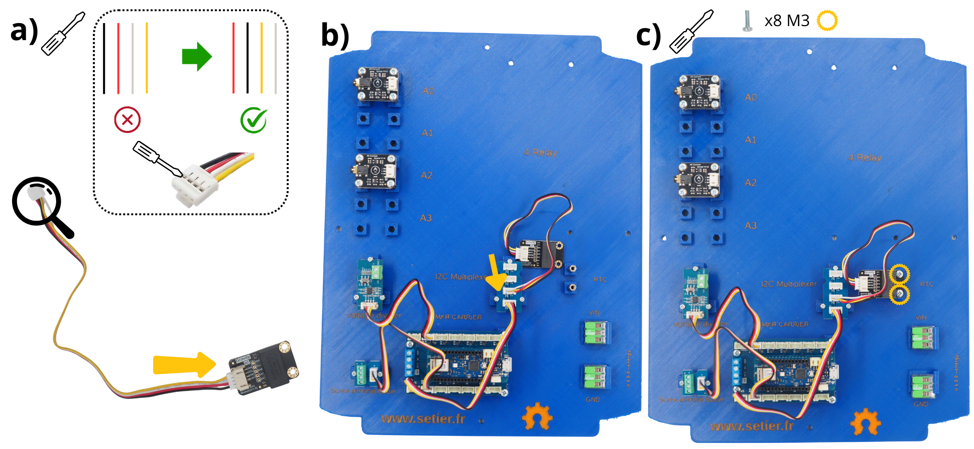
See also
To better understand how to reverse these cables, watch the following video: https://www.youtube.com/watch?v=0G7iIwfuaJ8
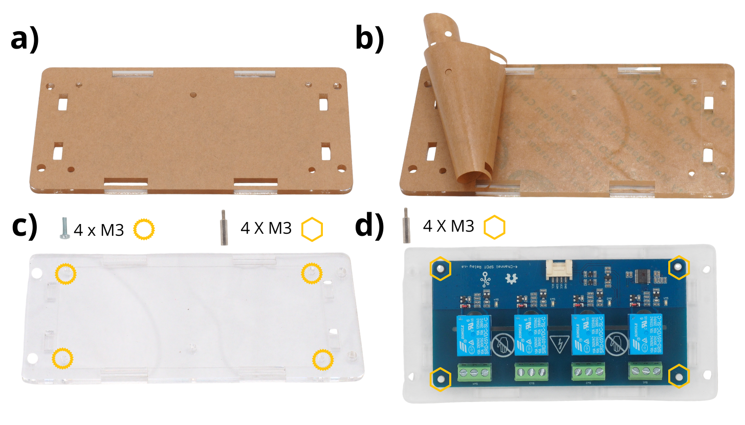
7. Assembling and installing the Grove 4-Relay Module#
The Grove 4-Relay Module allows you to manage the power supply to the sensors, and thus switch them off when they are not taking measurements.
Take the various Plexiglas components from the Grove 4-Relay Module.
Remove the protective tape from all these parts.
Take the bottom plate, then insert 4 M3 screws (supplied) from underneath. Next, fit 4 M3 5 mm spacers onto these same screws.
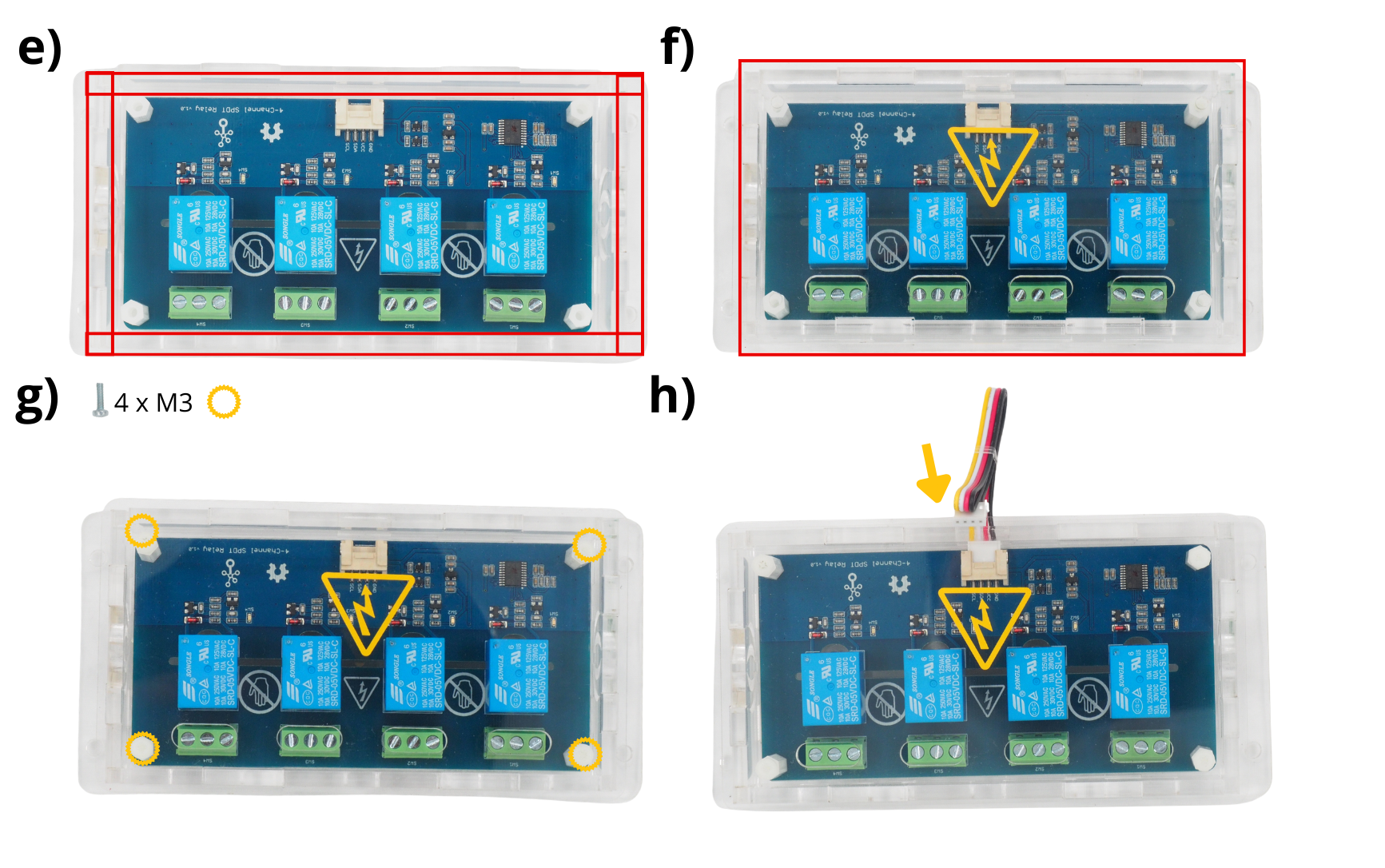
Place the circuit board on these spacers, then secure them using 2 cm M3 spacers (supplied).
Position the vertical Plexiglas pieces around the circuit board.
Place the Plexiglas cover onto the M3 spacers provided for this purpose, above the circuit board.
Secure it using M3 screws (supplied).
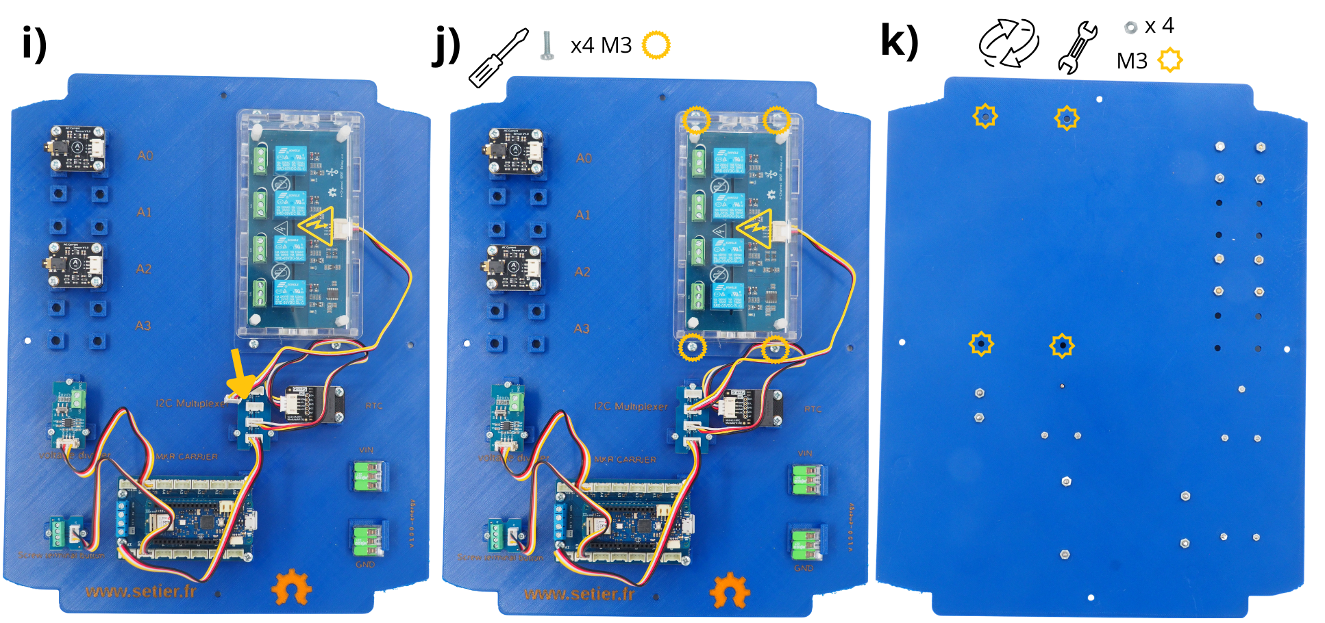
Connect the Grove connector supplied with the Grove 4-Relay Module.
Place the Grove 4-Relay Module in the designated sockets (labelled 4 relay).
Insert M3 screws into the holes provided.
Then turn the plate over and secure these screws using M3 nuts.
Step 3: Wiring the various circuit boards#
1. Connecting the power supply to Arduino boards#
Note
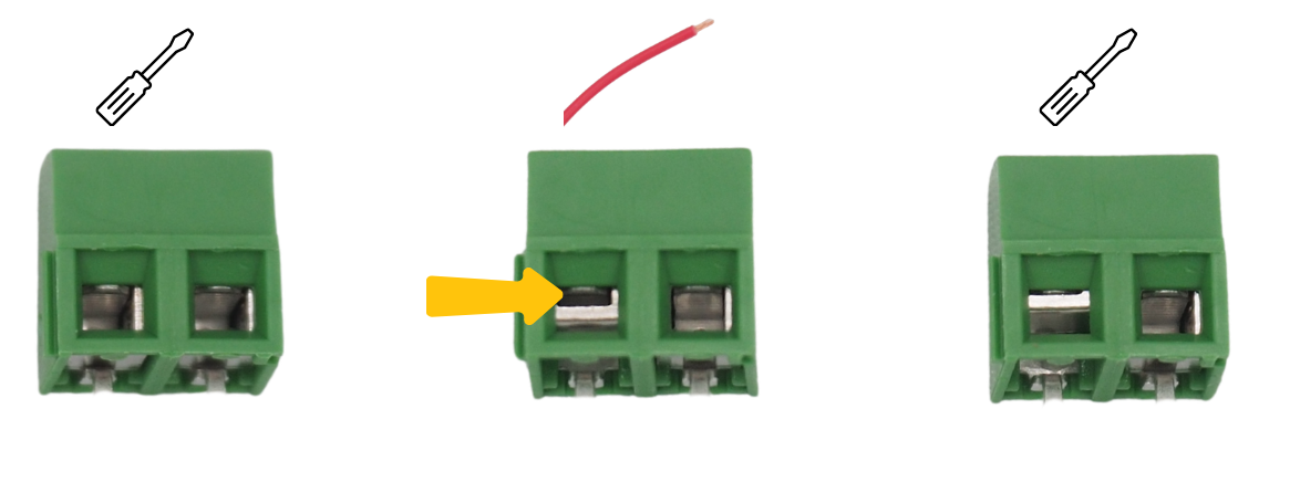
In the following steps, you will regularly be asked to insert cables into various screw terminals, and then tighten them. To do this, you must first unscrew the screw terminal block (see image) to open it, allowing you to insert a cable before screwing it back down to close the screw terminal block over the cable.
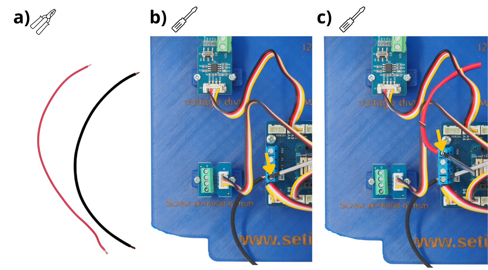
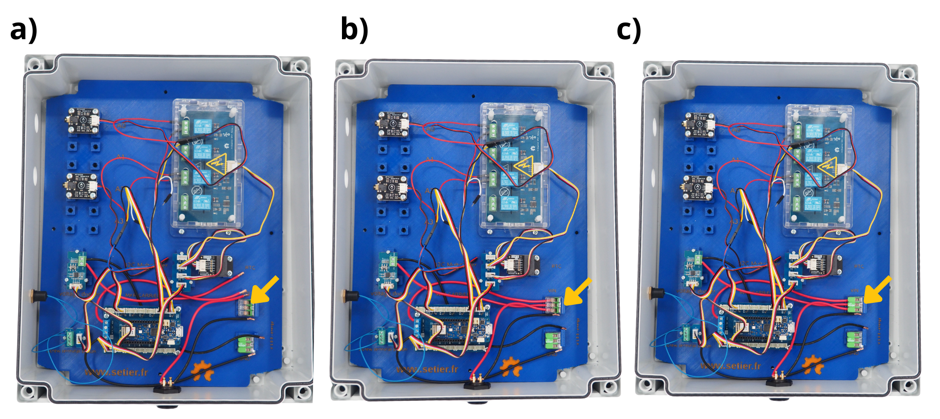
Cut and strip a 20 cm red wire and a 20 cm black wire.
Insert the black cable into the GND screw terminal on the Arduino MKR Connector Carrier, then tighten the screw.
Insert the red cable into the VIN screw terminal on the Arduino MKR Connector Carrier, then tighten the screw.
2. Connecting the voltage measurement to the Grove Voltage Divider Module#
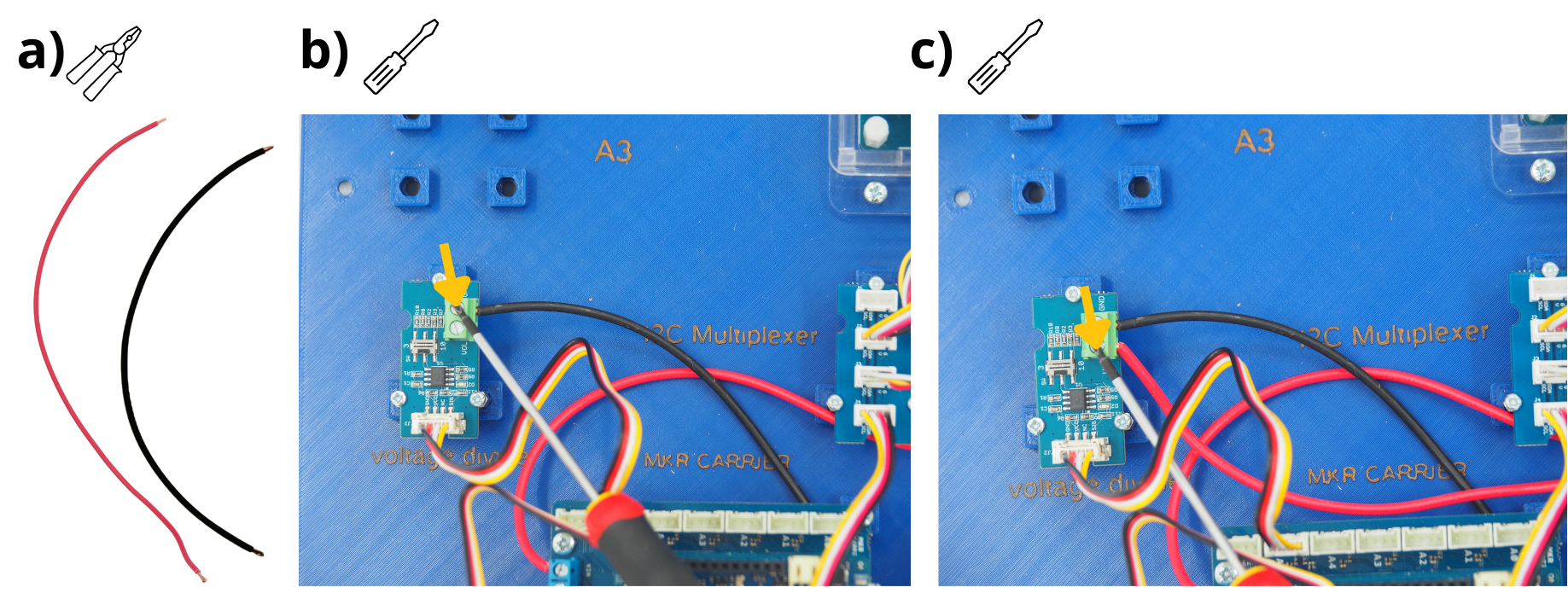
Cut a 15 cm length of red wire and a 15 cm length of black wire, then strip the ends using wire strippers.
Insert the black cable into the screw terminal block ‘GND’ on the Grove Voltage Divider Module and tighten the screw.
Insert the red cable into the screw terminal block ‘VOL’ on the Grove Voltage Divider Module and tighten the screw.
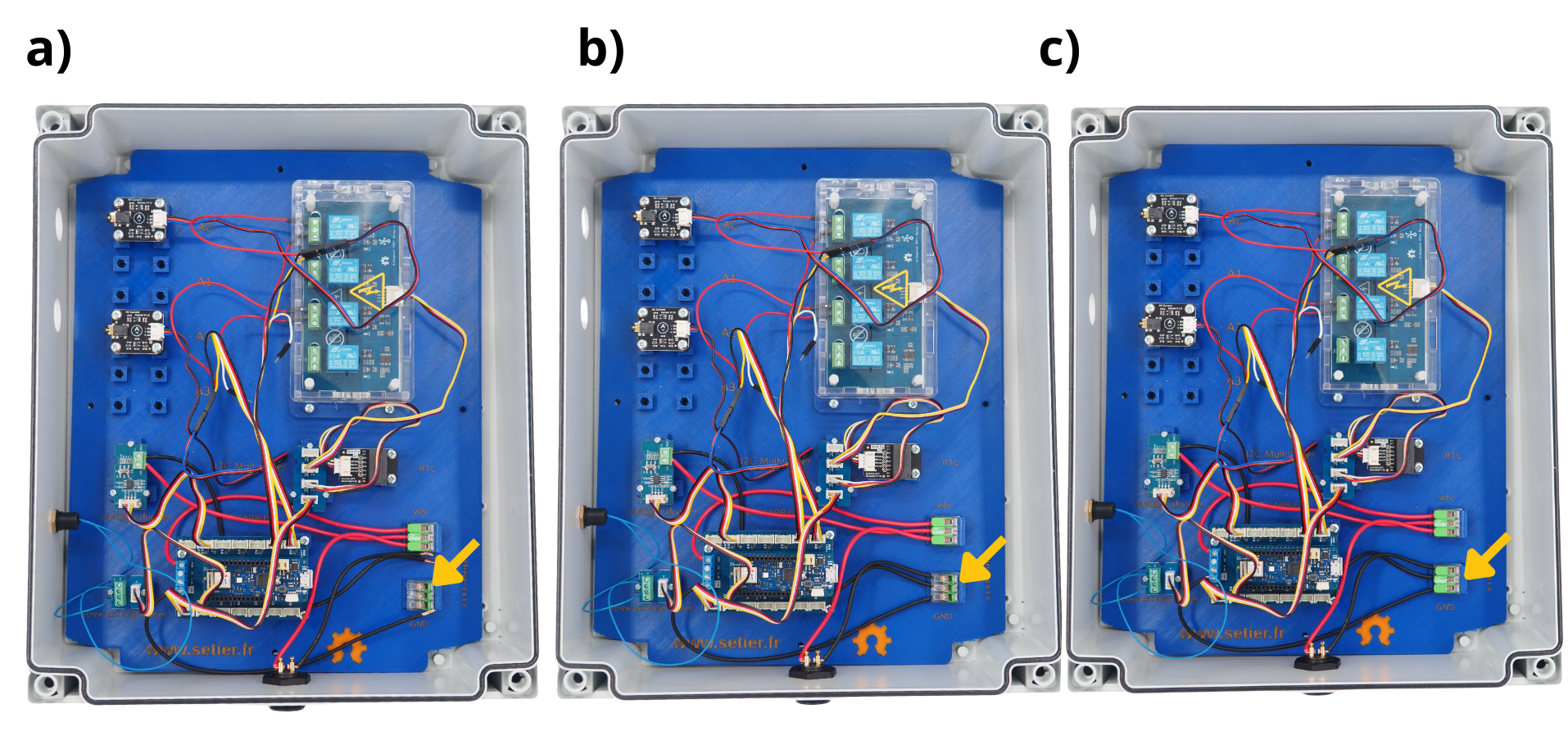
3. Connecting the energy sensors#
Using the cable prepared in step 2.2, connect the Grove end to one of the ‘A0’ to ‘A3’ ports (in this case, A2), and the other end to the sensor board mounted on the A2 spacer.
Take the red end of the jumper wire from the sensor board and insert it into the first hole of the third relay (i.e. the third port on the Arduino MKR Connector Carrier board), then screw it in.
Take the red end of the Grove Picot cable from port ‘A3’ and insert it into the second hole of the third relay, then screw it in.
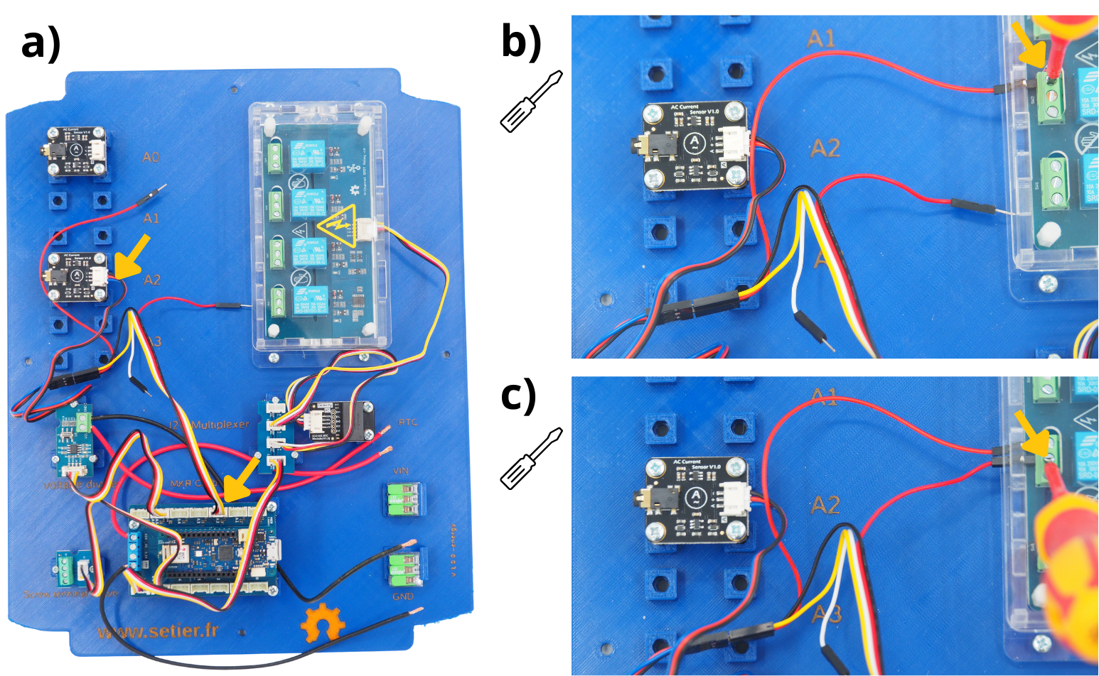
Using the cable prepared in step 2.2, connect the Grove end to one of the ‘A0’ to ‘A3’ ports (in this case, A0), and the other end to the sensor board mounted on the A0 spacer.
Take the red end of the jumper cable from the sensor board and insert it into the first hole of the first relay (as this is the first port on the Arduino MKR Connector Carrier board), then screw it in.
Take the red end of the Grove Picot cable from port ‘A0’ and insert it into the second hole of the first relay, then screw it in.
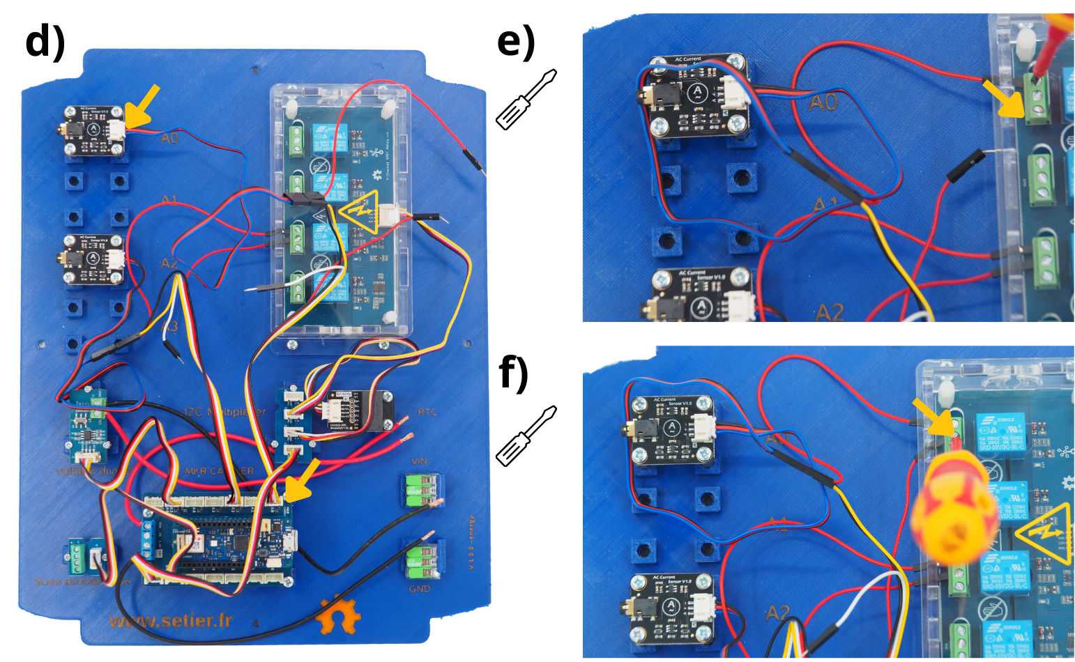
Perform steps g and h for all sensors connected to your system, using the subsequent relays.
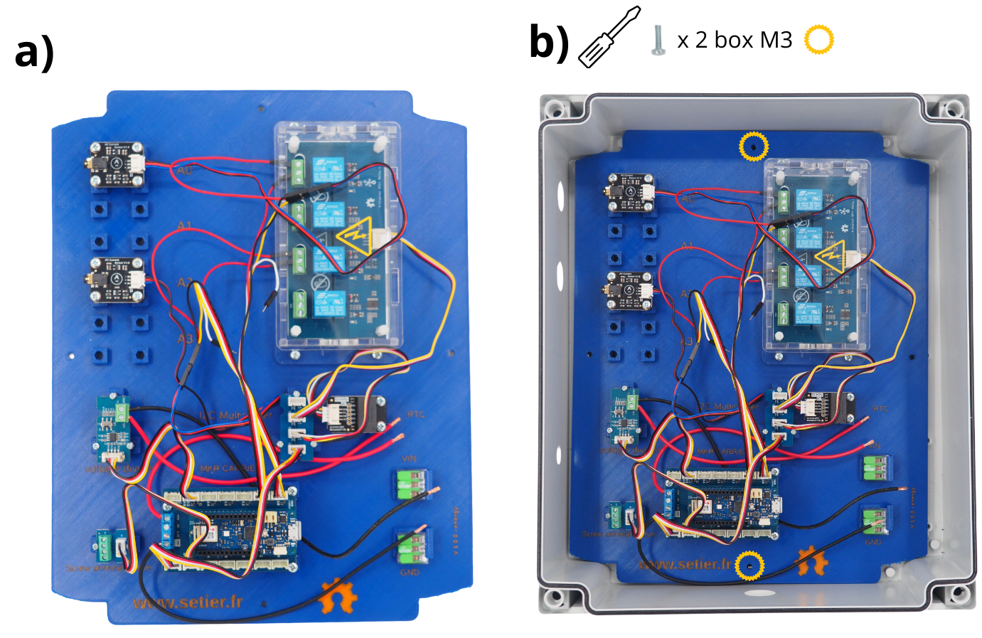
4. Fitting the plate inside the box#
Take the plate.
Place it in the box (see image). Secure it using the screws provided.
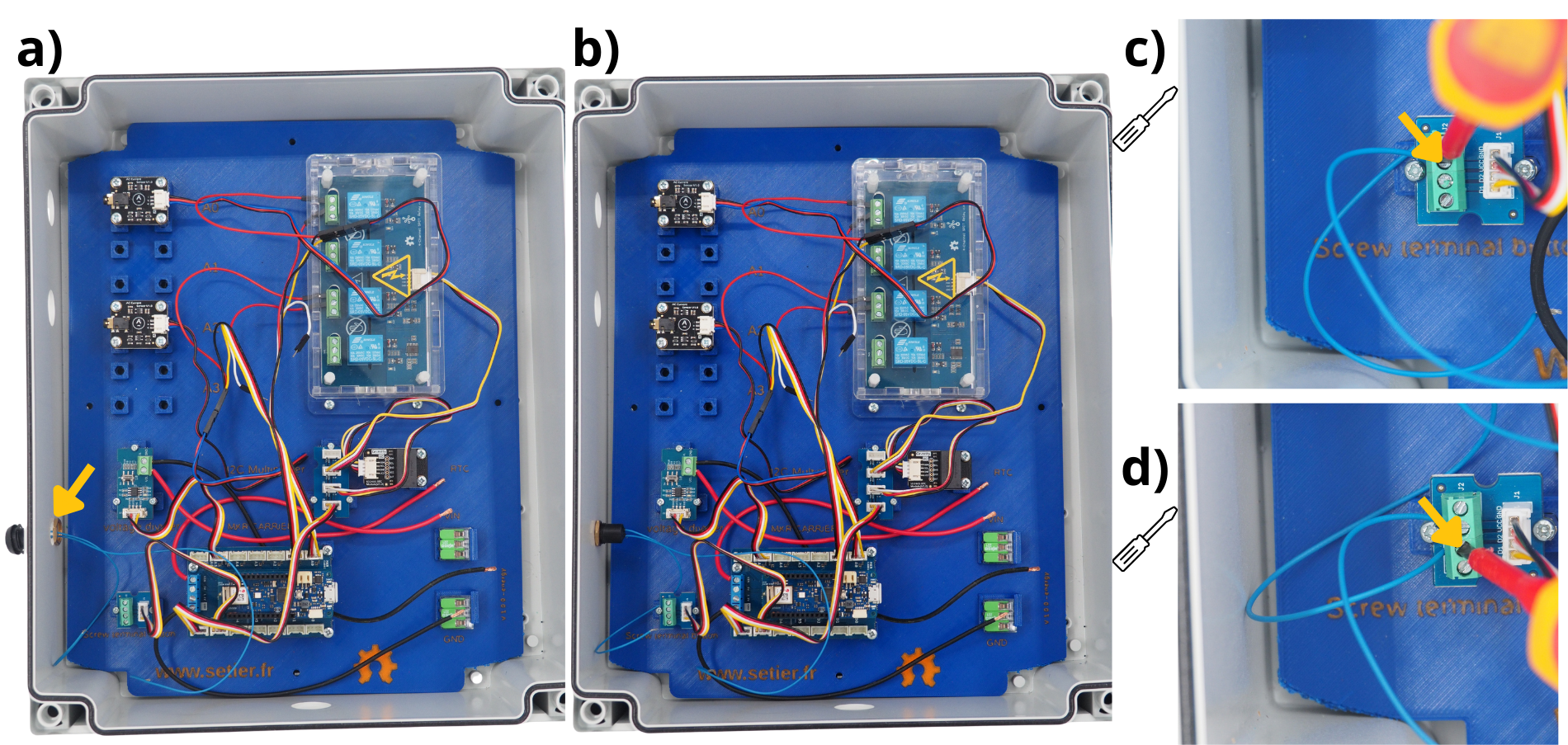
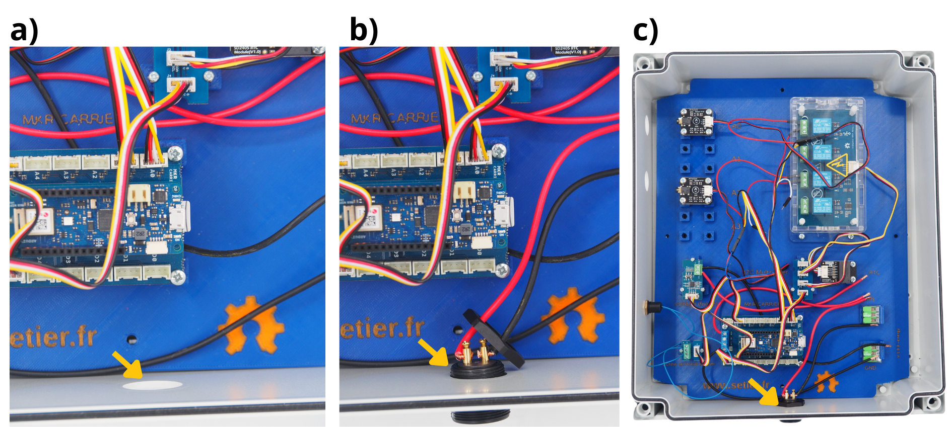
5. Connecting the push button#
Attention
The push-button seal must be positioned on the outside of the box.
Insert the push button into the hole provided.
Secure it.
Strip the end of one of the blue wires from the push button, then insert it into port ‘D2’ on the screw terminal block of the Grove Screw Terminal Module, and tighten the screw.
Strip the end of the other blue push-button cable, then insert it into the ‘D1’ port on the screw terminal block of the Grove Screw Terminal Module, and tighten the screw.
Step 4: Connecting the external power supply#
The next step involves wiring the power supply unit for the control unit. This unit must be plugged into a 220 V socket when using the Setier Control Unit.
Cut and strip a 20 cm red wire and a 20 cm black wire.
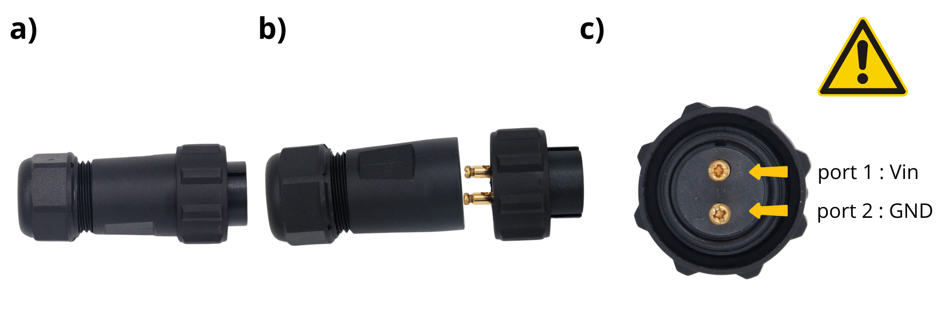
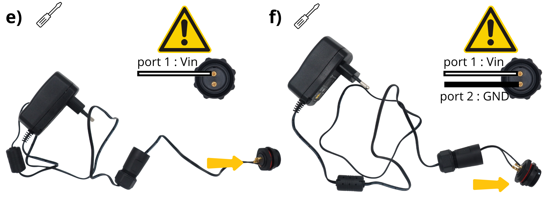
Take the through‑panel power connector.
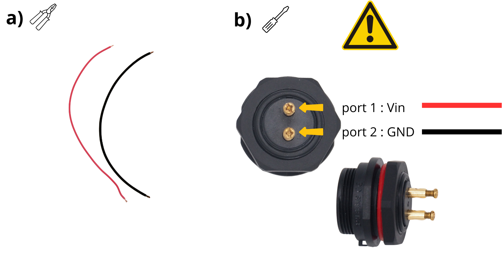
Insert one end of the red cable into the screw terminal ‘1’ on the panel power connector, then tighten the screw.
Insert one end of the black cable into the screw terminal ‘2’ on the panel power connector, then tighten the screw.
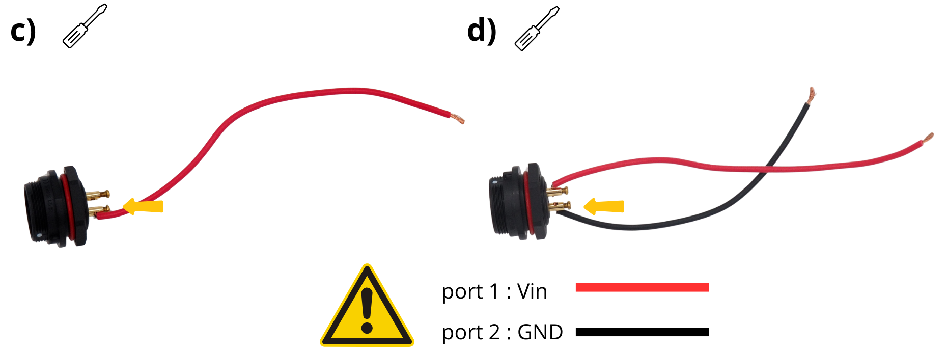
Attention
To prevent a short circuit between the GND cable (black) and the VIN cable (red), add a heat-shrink sleeve.
Take the through‑panel power connector.
Unscrew it to access the connection screws.
Follow the instructions marked around it (screw terminal block ‘1’ and screw terminal block ‘2’).
Take the 220 V – 12 V power plug, flip it, and set the output to 12 V using a screwdriver.
Trim the tip of this power plug.
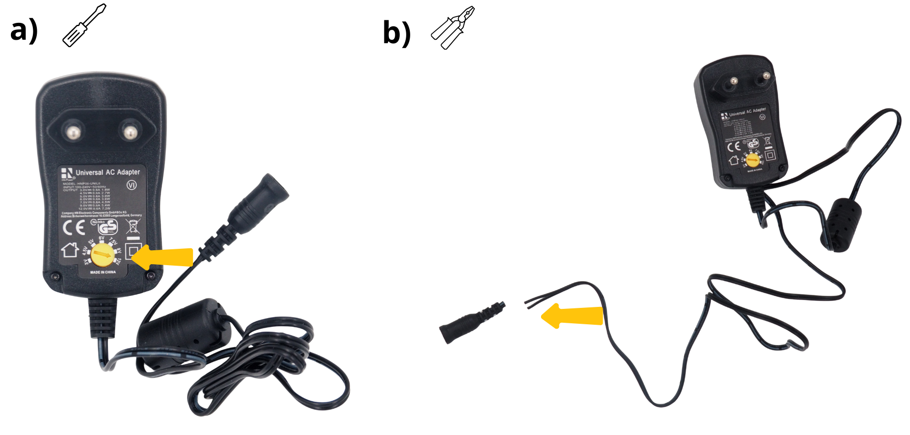
Strip the two wires at this same end.
Thread the grommet of the external power connector through.
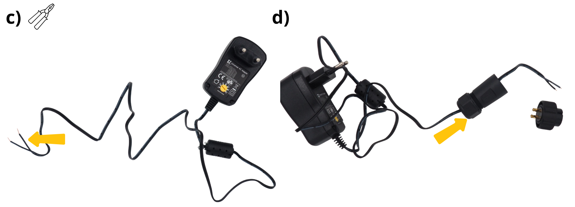
Suivez les instructions indiquées autour (bornier à vis « 1 » et bornier à vis « 2 »).
Insert the black cable into screw terminal ‘2’ on the panel power connector. Make sure you connect the correct cable to the correct screw terminal.
Screw the cable gland onto the connector you connected earlier.
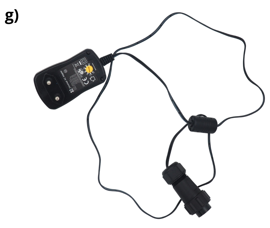
The power supply is now ready.
Take the power plug that you have already connected.
Insert it into the hole provided.
Secure it using the nut provided.
Step 5: Connecting the various power cables#
1. Connecting the 12 V power supply for the various components to a WAGO terminal block#
Open the three levers on the first WAGO terminal block.
Insert the remaining ends of the following red cables into each of these terminals: from the Grove Voltage Divider Module, from the power supply, and from the Arduino MKR Connector Carrier board.
Close the three levers connected to the WAGO terminal block.
2. Connecting the GND ground terminals of the various components to a WAGO terminal block#
Open the three levers on the first WAGO terminal block.
Insert the remaining ends of the following black cables into each of these terminals: from the Grove Voltage Divider Module, from the power supply, and from the Arduino MKR Connector Carrier board.
Close the three levers connected to the WAGO terminal block.
Step 6: Finishing the assembly#
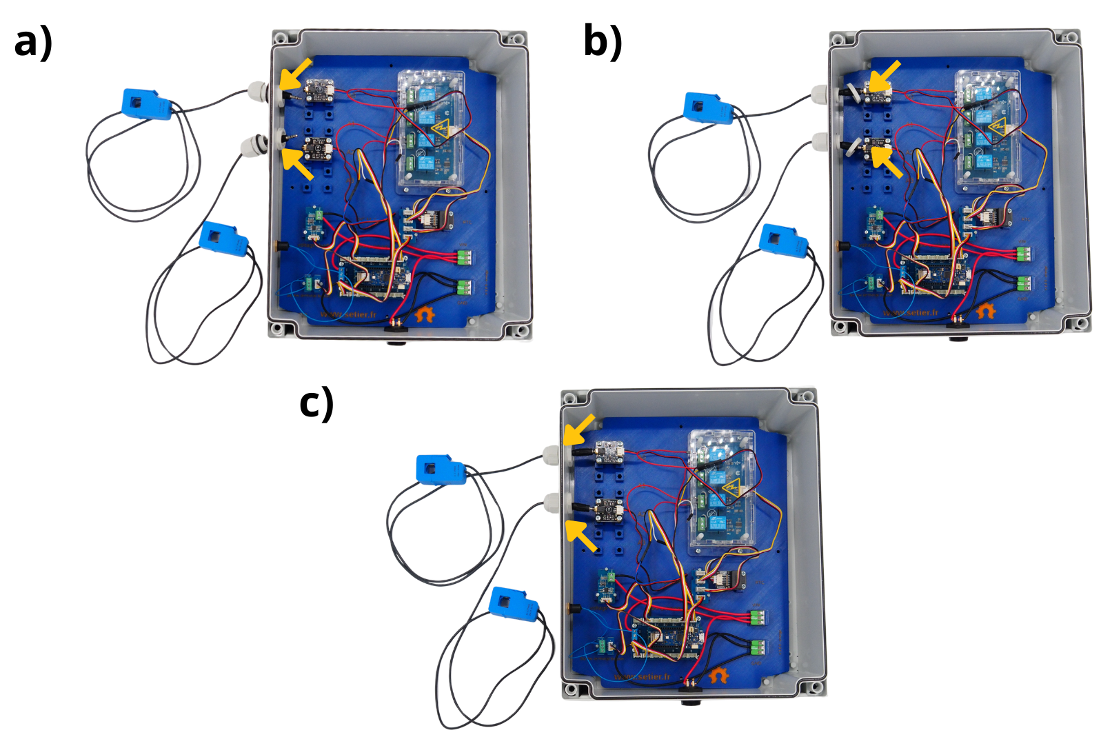
1. Connecting the energy sensors#
Note
Repeat these steps for each sensor you plan to connect.
Take the M16 cable gland.
Open it.
Take the Sensor.
Insert the sensor Jack connector into the bushings.
Insert the sensor Jack connector into the bushings.
Close the second part over the first part of the cable gland.
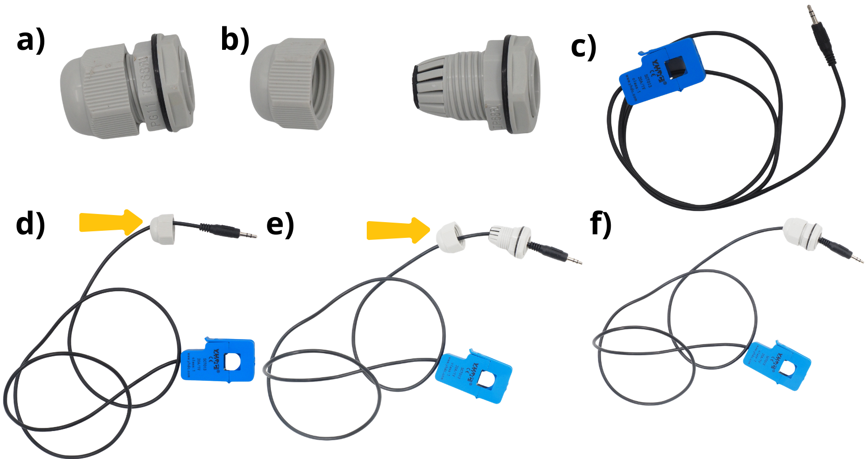
Insert the cable glands into the holes provided for this purpose.
Connect the sensor board to the sensor jacks.
Close the cable gland.
2. Plug in the socket and close the box.#
Take the 12 V plug for the central power supply and connect it to the power block.
Close the enclosure by screwing the cover with the four supplied screws.
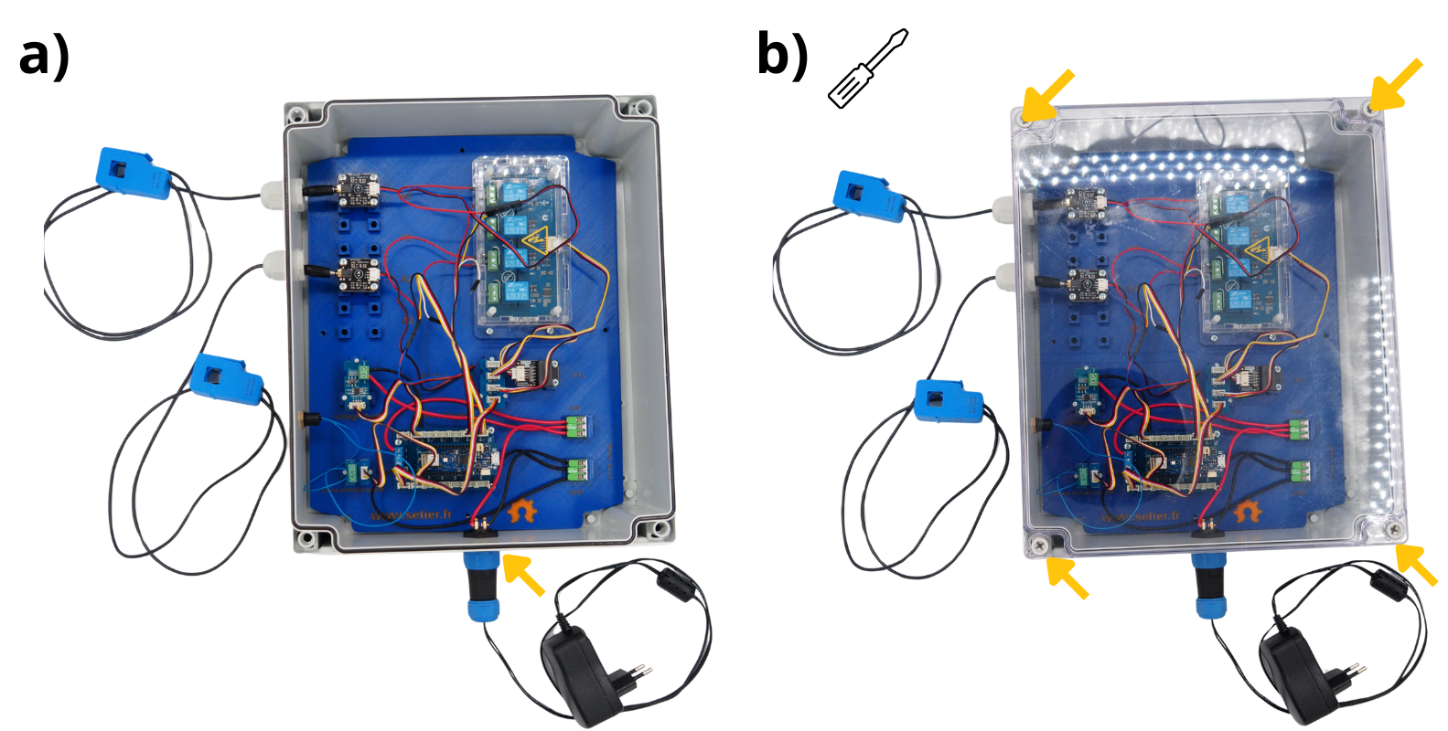
The Setier Power Station is ready to be programmed and then put inato operation.